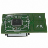
MA180025 Microchip Technology, MA180025 Datasheet - Page 303

MA180025
Manufacturer Part Number
MA180025
Description
MODULE PLUG-IN PIC18F87J90 PIM
Manufacturer
Microchip Technology
Series
PIC®r
Specifications of MA180025
Accessory Type
Plug-In Module (PIM) - PIC18F87J90
Product
Microcontroller Modules
Silicon Manufacturer
Microchip
Core Architecture
PIC
Core Sub-architecture
PIC18
Silicon Core Number
PIC18F
Silicon Family Name
PIC18FxxJxx
Lead Free Status / RoHS Status
Lead free / RoHS Compliant
For Use With/related Products
PICDEM LCD 2 Demonstration Board (DM163030)
For Use With
DM163030 - KIT DEV PICDEM LCD2
Lead Free Status / Rohs Status
Lead free / RoHS Compliant
Available stocks
Company
Part Number
Manufacturer
Quantity
Price
Company:
Part Number:
MA180025
Manufacturer:
Microchip Technology
Quantity:
135
Company:
Part Number:
MA180025
Manufacturer:
MICROCHIP
Quantity:
12 000
- Current page: 303 of 450
- Download datasheet (4Mb)
22.9
A simplified circuit for an analog input is shown in
Figure 22-4. Since the analog pins are connected to a
digital output, they have reverse biased diodes to V
and V
V
FIGURE 22-4:
TABLE 22-1:
2010 Microchip Technology Inc.
INTCON
PIR2
PIE2
IPR2
CMCON
CVRCON
PORTF
LATF
TRISF
Legend: — = unimplemented, read as ‘0’. Shaded cells are unused by the comparator module.
SS
Name
and V
SS
. The analog input, therefore, must be between
Analog Input Connection
Considerations
DD
. If the input voltage deviates from this
VA
GIE/GIEH PEIE/GIEL TMR0IE
OSCFIF
OSCFIE
OSCFIP
CVREN
C2OUT
TRISF7
LATF7
Bit 7
RF7
REGISTERS ASSOCIATED WITH COMPARATOR MODULE
R
S
Legend:
< 10k
COMPARATOR ANALOG INPUT MODEL
A
CVROE
C1OUT
TRISF6
IN
LATF6
CMIE
CMIP
CMIF
Bit 6
RF6
C
V
I
R
R
VA
LEAKAGE
C
5 pF
T
PIN
IC
S
PIN
TRISF5
C2INV
LATF5
CVRR
Bit 5
RF5
= Input Capacitance
= Threshold Voltage
= Leakage Current at the pin due to various junctions
= Interconnect Resistance
= Source Impedance
= Analog Voltage
—
—
—
V
DD
CVRSS
TRISF4
INT0IE
C1INV
LATF4
DD
Bit 4
RF4
—
—
—
V
V
T
T
= 0.6V
= 0.6V
PIC18F87J90 FAMILY
TRISF3
range by more than 0.6V in either direction, one of the
diodes is forward biased and a latch-up condition may
occur. A maximum source impedance of 10 k is
recommended for the analog sources. Any external
component connected to an analog input pin, such as
a capacitor or a Zener diode, should have very little
leakage current.
BCLIF
BCLIE
BCLIP
LATF3
CVR3
RBIE
Bit 3
RF3
CIS
I
±100 nA
V
LEAKAGE
TMR0IF
SS
TRISF2
LATF2
LVDIF
LVDIE
LVDIP
CVR2
Bit 2
CM2
RF2
R
IC
TMR3IF
TMR3IE
TMR3IP
TRISF1
INT0IF
LATF1
CVR1
Bit 1
CM1
RF1
Comparator
Input
CVR0
DS39933D-page 303
RBIF
Bit 0
CM0
—
—
—
—
—
—
on page
Values
Reset
59
62
62
62
61
61
62
62
62
Related parts for MA180025
Image
Part Number
Description
Manufacturer
Datasheet
Request
R

Part Number:
Description:
Manufacturer:
Microchip Technology Inc.
Datasheet:

Part Number:
Description:
Manufacturer:
Microchip Technology Inc.
Datasheet:

Part Number:
Description:
Manufacturer:
Microchip Technology Inc.
Datasheet:

Part Number:
Description:
Manufacturer:
Microchip Technology Inc.
Datasheet:

Part Number:
Description:
Manufacturer:
Microchip Technology Inc.
Datasheet:

Part Number:
Description:
Manufacturer:
Microchip Technology Inc.
Datasheet:

Part Number:
Description:
Manufacturer:
Microchip Technology Inc.
Datasheet:

Part Number:
Description:
Manufacturer:
Microchip Technology Inc.
Datasheet:


