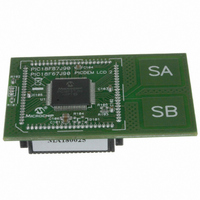
MA180025 Microchip Technology, MA180025 Datasheet - Page 312

MA180025
Manufacturer Part Number
MA180025
Description
MODULE PLUG-IN PIC18F87J90 PIM
Manufacturer
Microchip Technology
Series
PIC®r
Specifications of MA180025
Accessory Type
Plug-In Module (PIM) - PIC18F87J90
Product
Microcontroller Modules
Silicon Manufacturer
Microchip
Core Architecture
PIC
Core Sub-architecture
PIC18
Silicon Core Number
PIC18F
Silicon Family Name
PIC18FxxJxx
Lead Free Status / RoHS Status
Lead free / RoHS Compliant
For Use With/related Products
PICDEM LCD 2 Demonstration Board (DM163030)
For Use With
DM163030 - KIT DEV PICDEM LCD2
Lead Free Status / Rohs Status
Lead free / RoHS Compliant
Available stocks
Company
Part Number
Manufacturer
Quantity
Price
Company:
Part Number:
MA180025
Manufacturer:
Microchip Technology
Quantity:
135
Company:
Part Number:
MA180025
Manufacturer:
MICROCHIP
Quantity:
12 000
- Current page: 312 of 450
- Download datasheet (4Mb)
PIC18F87J90 FAMILY
The CTMU current source may be trimmed with the
trim bits in CTMUICON using an iterative process to get
an exact desired current. Alternatively, the nominal
value without adjustment may be used; it may be
stored by the software for use in all subsequent
capacitive or time measurements.
To calculate the value for R
must be chosen and then the resistance can be
calculated. For example, if the A/D Converter reference
voltage is 3.3V, use 70% of full scale or 2.31V as the
desired approximate voltage to be read by the A/D
Converter. If the range of the CTMU current source is
selected to be 0.55 A, the resistor value needed is cal-
culated as R
Similarly, if the current source is chosen to be 5.5 A,
R
source is set to 55 A.
FIGURE 24-2:
DS39933D-page 312
CAL
would be 420,000Ω, and 42,000Ω if the current
ANx
R
CAL
CAL
= 2.31V/0.55 A for a value of 4.2 MΩ.
CTMU CURRENT SOURCE
CALIBRATION CIRCUIT
Current Source
MUX
PIC18F87J90
CAL
A/D Converter
, the nominal current
A/D
A/D
Trigger
CTMU
manually triggers the A/D Converter. This is done to
demonstrate the entire stepwise process. It is also
possible to automatically trigger the conversion by
setting the CTMU’s CTTRIG bit (CTMUCONH<0>).
A value of 70% of full-scale voltage is chosen to make
sure that the A/D Converter is in a range that is well
above the noise floor. Keep in mind that if an exact cur-
rent is chosen to incorporate the trimming bits from
CTMUICON, the resistor value of R
adjusted accordingly. R
allow for available resistor values. R
the highest precision available, keeping in mind the
amount of precision needed for the circuit that the
CTMU will be used to measure. A recommended
minimum would be 0.1% tolerance.
The following examples show one typical method for
performing a CTMU current calibration. Example 24-1
demonstrates how to initialize the A/D Converter and the
CTMU; this routine is typical for applications using both
modules. Example 24-2 demonstrates one method for
the actual calibration routine. Note that this method
2010 Microchip Technology Inc.
CAL
may be also adjusted to
CAL
CAL
may need to be
should be of
Related parts for MA180025
Image
Part Number
Description
Manufacturer
Datasheet
Request
R

Part Number:
Description:
Manufacturer:
Microchip Technology Inc.
Datasheet:

Part Number:
Description:
Manufacturer:
Microchip Technology Inc.
Datasheet:

Part Number:
Description:
Manufacturer:
Microchip Technology Inc.
Datasheet:

Part Number:
Description:
Manufacturer:
Microchip Technology Inc.
Datasheet:

Part Number:
Description:
Manufacturer:
Microchip Technology Inc.
Datasheet:

Part Number:
Description:
Manufacturer:
Microchip Technology Inc.
Datasheet:

Part Number:
Description:
Manufacturer:
Microchip Technology Inc.
Datasheet:

Part Number:
Description:
Manufacturer:
Microchip Technology Inc.
Datasheet:


