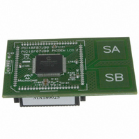
MA180025 Microchip Technology, MA180025 Datasheet - Page 438

MA180025
Manufacturer Part Number
MA180025
Description
MODULE PLUG-IN PIC18F87J90 PIM
Manufacturer
Microchip Technology
Series
PIC®r
Specifications of MA180025
Accessory Type
Plug-In Module (PIM) - PIC18F87J90
Product
Microcontroller Modules
Silicon Manufacturer
Microchip
Core Architecture
PIC
Core Sub-architecture
PIC18
Silicon Core Number
PIC18F
Silicon Family Name
PIC18FxxJxx
Lead Free Status / RoHS Status
Lead free / RoHS Compliant
For Use With/related Products
PICDEM LCD 2 Demonstration Board (DM163030)
For Use With
DM163030 - KIT DEV PICDEM LCD2
Lead Free Status / Rohs Status
Lead free / RoHS Compliant
Available stocks
Company
Part Number
Manufacturer
Quantity
Price
Company:
Part Number:
MA180025
Manufacturer:
Microchip Technology
Quantity:
135
Company:
Part Number:
MA180025
Manufacturer:
MICROCHIP
Quantity:
12 000
- Current page: 438 of 450
- Download datasheet (4Mb)
PIC18F87J90 FAMILY
F
Fail-Safe Clock Monitor............................................. 325, 335
Fast Register Stack............................................................. 69
Firmware Instructions........................................................ 339
Flash Configuration Words................................................ 325
Flash Program Memory....................................................... 89
FSCM. See Fail-Safe Clock Monitor.
G
GOTO................................................................................ 360
H
Hardware Multiplier ............................................................. 99
I
I/O Ports ............................................................................ 117
I
DS39933D-page 438
2
C Mode (MSSP) ............................................................. 220
Exiting Fail-Safe Operation ....................................... 336
Interrupts in Power-Managed Modes ........................ 336
POR or Wake-up From Sleep ................................... 336
WDT During Oscillator Failure .................................. 335
Associated Registers .................................................. 98
Control Registers ........................................................ 90
Erase Sequence ......................................................... 94
Erasing ........................................................................ 94
Operation During Code-Protect .................................. 98
Reading....................................................................... 93
Table Pointer
Table Pointer Boundaries ........................................... 92
Table Reads and Table Writes ................................... 89
Write Sequence .......................................................... 95
Write Sequence (Word Programming) ........................ 97
Writing ......................................................................... 95
8 x 8 Multiplication Algorithms .................................... 99
Operation .................................................................... 99
Performance Comparison (table) ................................ 99
Input Voltage Considerations .................................... 117
Open-Drain Outputs .................................................. 118
Output Pin Drive........................................................ 117
Pin Capabilities ......................................................... 117
Pull-up Configuration ................................................ 118
Acknowledge Sequence Timing................................ 248
Associated Registers ................................................ 254
Baud Rate Generator ................................................ 241
Bus Collision
Clock Arbitration........................................................ 242
Clock Stretching ........................................................ 234
Clock Synchronization and the CKP Bit .................... 235
Effects of a Reset...................................................... 249
General Call Address Support .................................. 238
I
2
C Clock Rate w/BRG .............................................. 241
EECON1 and EECON2 ...................................... 90
TABLAT (Table Latch) Register.......................... 92
TBLPTR (Table Pointer) Register ....................... 92
Boundaries Based on Operation......................... 92
Unexpected Termination..................................... 98
Write Verify ......................................................... 98
During a Repeated Start Condition ................... 252
During a Stop Condition.................................... 253
10-Bit Slave Receive Mode (SEN = 1).............. 234
10-Bit Slave Transmit Mode.............................. 234
7-Bit Slave Receive Mode (SEN = 1)................ 234
7-Bit Slave Transmit Mode................................ 234
INCF ................................................................................. 360
INCFSZ............................................................................. 361
In-Circuit Debugger........................................................... 337
In-Circuit Serial Programming (ICSP)....................... 325, 337
Indexed Literal Offset Addressing
Indexed Literal Offset Mode.............................................. 386
Indirect Addressing ............................................................. 83
INFSNZ............................................................................. 361
Initialization Conditions for all Registers ....................... 59–64
Instruction Cycle ................................................................. 70
Instruction Set................................................................... 339
Master Mode............................................................. 239
Multi-Master Communication, Bus Collision
Multi-Master Mode .................................................... 249
Operation .................................................................. 225
Read/Write Bit Information (R/W Bit) ................ 225, 227
Registers .................................................................. 220
Serial Clock (SCK/SCL)............................................ 227
Slave Mode............................................................... 225
Sleep Operation........................................................ 249
Stop Condition Timing .............................................. 248
and Standard PIC18 Instructions.............................. 386
Clocking Scheme........................................................ 70
Flow/Pipelining............................................................ 70
ADDLW..................................................................... 345
ADDWF..................................................................... 345
ADDWF (Indexed Literal Offset Mode) ..................... 387
ADDWFC .................................................................. 346
ANDLW..................................................................... 346
ANDWF..................................................................... 347
BC............................................................................. 347
BCF .......................................................................... 348
BN............................................................................. 348
BNC .......................................................................... 349
BNN .......................................................................... 349
BNOV ....................................................................... 350
BNZ .......................................................................... 350
BOV .......................................................................... 353
BRA .......................................................................... 351
BSF........................................................................... 351
BSF (Indexed Literal Offset Mode) ........................... 387
BTFSC ...................................................................... 352
BTFSS ...................................................................... 352
BTG .......................................................................... 353
BZ ............................................................................. 354
CALL......................................................................... 354
CLRF ........................................................................ 355
CLRWDT .................................................................. 355
COMF ....................................................................... 356
CPFSEQ ................................................................... 356
CPFSGT ................................................................... 357
CPFSLT .................................................................... 357
Baud Rate Generator ....................................... 241
Operation.......................................................... 240
Reception ......................................................... 245
Repeated Start Condition Timing ..................... 244
Start Condition Timing ...................................... 243
Transmission .................................................... 245
and Arbitration .................................................. 249
Address Masking .............................................. 226
Addressing........................................................ 225
Reception ......................................................... 227
Transmission .................................................... 227
2010 Microchip Technology Inc.
Related parts for MA180025
Image
Part Number
Description
Manufacturer
Datasheet
Request
R

Part Number:
Description:
Manufacturer:
Microchip Technology Inc.
Datasheet:

Part Number:
Description:
Manufacturer:
Microchip Technology Inc.
Datasheet:

Part Number:
Description:
Manufacturer:
Microchip Technology Inc.
Datasheet:

Part Number:
Description:
Manufacturer:
Microchip Technology Inc.
Datasheet:

Part Number:
Description:
Manufacturer:
Microchip Technology Inc.
Datasheet:

Part Number:
Description:
Manufacturer:
Microchip Technology Inc.
Datasheet:

Part Number:
Description:
Manufacturer:
Microchip Technology Inc.
Datasheet:

Part Number:
Description:
Manufacturer:
Microchip Technology Inc.
Datasheet:


