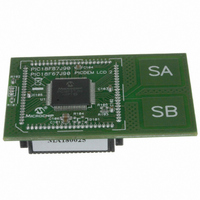
MA180025 Microchip Technology, MA180025 Datasheet - Page 443

MA180025
Manufacturer Part Number
MA180025
Description
MODULE PLUG-IN PIC18F87J90 PIM
Manufacturer
Microchip Technology
Series
PIC®r
Specifications of MA180025
Accessory Type
Plug-In Module (PIM) - PIC18F87J90
Product
Microcontroller Modules
Silicon Manufacturer
Microchip
Core Architecture
PIC
Core Sub-architecture
PIC18
Silicon Core Number
PIC18F
Silicon Family Name
PIC18FxxJxx
Lead Free Status / RoHS Status
Lead free / RoHS Compliant
For Use With/related Products
PICDEM LCD 2 Demonstration Board (DM163030)
For Use With
DM163030 - KIT DEV PICDEM LCD2
Lead Free Status / Rohs Status
Lead free / RoHS Compliant
Available stocks
Company
Part Number
Manufacturer
Quantity
Price
Company:
Part Number:
MA180025
Manufacturer:
Microchip Technology
Quantity:
135
Company:
Part Number:
MA180025
Manufacturer:
MICROCHIP
Quantity:
12 000
- Current page: 443 of 450
- Download datasheet (4Mb)
RTCEN Bit Write ............................................................... 165
S
SCK................................................................................... 211
SDI .................................................................................... 211
SDO .................................................................................. 211
SEC_IDLE Mode................................................................. 50
SEC_RUN Mode ................................................................. 46
Serial Clock, SCK ............................................................. 211
Serial Data In (SDI) ........................................................... 211
Serial Data Out (SDO) ...................................................... 211
Serial Peripheral Interface. See SPI Mode.
SETF ................................................................................. 373
Slave Select (SS) .............................................................. 211
SLEEP .............................................................................. 374
Software Simulator (MPLAB SIM)..................................... 391
Special Event Trigger. See Compare (CCP Module).
Special Features of the CPU ............................................ 325
SPI Mode (MSSP)
SS ..................................................................................... 211
SSPOV.............................................................................. 245
SSPOV Status Flag .......................................................... 245
SSPSTAT Register
Stack Full/Underflow Resets ............................................... 69
SUBFSR ........................................................................... 385
SUBFWB........................................................................... 374
SUBLW ............................................................................. 375
SUBULNK ......................................................................... 385
SUBWF ............................................................................. 375
SUBWFB........................................................................... 376
SWAPF ............................................................................. 376
2010 Microchip Technology Inc.
Operation
Register Interface...................................................... 165
Register Maps........................................................... 171
Reset......................................................................... 170
Sleep Mode............................................................... 170
Value Registers (RTCVAL) ....................................... 160
Associated Registers ................................................ 219
Bus Mode Compatibility ............................................ 219
Effects of a Reset...................................................... 219
Enabling SPI I/O ....................................................... 215
Master Mode ............................................................. 216
Operation .................................................................. 214
Operation in Power-Managed Modes ....................... 219
Serial Clock............................................................... 211
Serial Data In ............................................................ 211
Serial Data Out ......................................................... 211
Slave Mode ............................................................... 217
Slave Select .............................................................. 211
Slave Select Synchronization ................................... 217
SPI Clock .................................................................. 216
Typical Connection ................................................... 215
R/W Bit.............................................................. 225, 227
Calibration......................................................... 168
Clock Source .................................................... 166
Digit Carry Rules............................................... 166
General Functionality ........................................ 167
Leap Year ......................................................... 167
Register Mapping.............................................. 167
Safety Window for Register Reads
Write Lock ......................................................... 167
Device ............................................................... 170
Power-on Reset (POR) ..................................... 170
ALRMVAL ................................................. 168
RTCVAL.................................................... 167
and Writes................................................. 167
PIC18F87J90 FAMILY
T
Table Pointer Operations (table)......................................... 92
Table Reads/Table Writes .................................................. 69
TBLRD .............................................................................. 377
TBLWT ............................................................................. 378
Timer0 .............................................................................. 139
Timer1 .............................................................................. 143
Timer2 .............................................................................. 149
Timer3 .............................................................................. 151
Timing Diagrams
Associated Registers................................................ 141
Clock Source Select (T0CS Bit) ............................... 140
Operation.................................................................. 140
Overflow Interrupt ..................................................... 141
Prescaler .................................................................. 141
Prescaler Assignment (PSA Bit)............................... 141
Prescaler Select (T0PS2:T0PS0 Bits) ...................... 141
Prescaler. See Prescaler, Timer0.
Reads and Writes in 16-Bit Mode............................. 140
Source Edge Select (T0SE Bit) ................................ 140
16-Bit Read/Write Mode ........................................... 145
Associated Registers................................................ 147
Interrupt .................................................................... 146
Operation.................................................................. 144
Oscillator........................................................... 143, 145
Oscillator as Secondary Clock.................................... 37
Overflow Interrupt ..................................................... 143
Resetting, Using the CCP Special
TMR1H Register....................................................... 143
TMR1L Register ....................................................... 143
Use as a Clock Source ............................................. 145
Use as a Real-Time Clock ........................................ 146
Associated Registers................................................ 150
Interrupt .................................................................... 150
Operation.................................................................. 149
Output....................................................................... 150
PR2 Register ............................................................ 179
TMR2 to PR2 Match Interrupt................................... 179
16-Bit Read/Write Mode ........................................... 153
Associated Registers................................................ 153
Operation.................................................................. 152
Oscillator........................................................... 151, 153
Overflow Interrupt ............................................. 151, 153
Special Event Trigger (CCP) .................................... 153
TMR3H Register....................................................... 151
TMR3L Register ....................................................... 151
A/D Conversion ........................................................ 426
Acknowledge Sequence ........................................... 248
Asynchronous Reception.................................. 267, 283
Asynchronous Transmission ............................ 265, 281
Asynchronous Transmission
Automatic Baud Rate Calculation............................. 263
Auto-Wake-up Bit (WUE) During
Auto-Wake-up Bit (WUE) During Sleep.................... 268
Baud Rate Generator with Clock Arbitration............. 242
BRG Overflow Sequence ......................................... 263
BRG Reset Due to SDA Arbitration During
Bus Collision During a Repeated Start
Switching Assignment ...................................... 141
Layout Considerations...................................... 146
Event Trigger .................................................... 146
(Back to Back) .......................................... 265, 281
Normal Operation ............................................. 268
Start Condition.................................................. 251
Condition (Case 1)............................................ 252
DS39933D-page 443
Related parts for MA180025
Image
Part Number
Description
Manufacturer
Datasheet
Request
R

Part Number:
Description:
Manufacturer:
Microchip Technology Inc.
Datasheet:

Part Number:
Description:
Manufacturer:
Microchip Technology Inc.
Datasheet:

Part Number:
Description:
Manufacturer:
Microchip Technology Inc.
Datasheet:

Part Number:
Description:
Manufacturer:
Microchip Technology Inc.
Datasheet:

Part Number:
Description:
Manufacturer:
Microchip Technology Inc.
Datasheet:

Part Number:
Description:
Manufacturer:
Microchip Technology Inc.
Datasheet:

Part Number:
Description:
Manufacturer:
Microchip Technology Inc.
Datasheet:

Part Number:
Description:
Manufacturer:
Microchip Technology Inc.
Datasheet:


