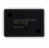
DF2328BVF25V Renesas Electronics America, DF2328BVF25V Datasheet - Page 18

DF2328BVF25V
Manufacturer Part Number
DF2328BVF25V
Description
IC H8S MCU FLASH 256K 128QFP
Manufacturer
Renesas Electronics America
Series
H8® H8S/2300r
Datasheets
1.HEWH8E10A.pdf
(19 pages)
2.D12312SVTE25V.pdf
(341 pages)
3.D12322RVF25V.pdf
(1304 pages)
Specifications of DF2328BVF25V
Core Processor
H8S/2000
Core Size
16-Bit
Speed
25MHz
Connectivity
SCI, SmartCard
Peripherals
DMA, POR, PWM, WDT
Number Of I /o
87
Program Memory Size
256KB (256K x 8)
Program Memory Type
FLASH
Ram Size
8K x 8
Voltage - Supply (vcc/vdd)
2.7 V ~ 3.6 V
Data Converters
A/D 8x10b; D/A 2x8b
Oscillator Type
Internal
Operating Temperature
-20°C ~ 75°C
Package / Case
128-QFP
For Use With
EDK2329 - DEV EVALUATION KIT H8S/2329
Lead Free Status / RoHS Status
Lead free / RoHS Compliant
Eeprom Size
-
Other names
HD64F2328BVF25V
Available stocks
Company
Part Number
Manufacturer
Quantity
Price
Company:
Part Number:
DF2328BVF25V
Manufacturer:
Renesas Electronics America
Quantity:
10 000
- Current page: 18 of 1304
- Download datasheet (8Mb)
7.3
7.4
7.5
7.6
7.7
Section 8 Data Transfer Controller....................................................................311
8.1
8.2
Rev.6.00 Sep. 27, 2007 Page xvi of xxx
REJ09B0220-0600
7.2.4
7.2.5
Register Descriptions (2) (Full Address Mode) ................................................................ 237
7.3.1
7.3.2
7.3.3
7.3.4
7.3.5
Register Descriptions (3) .................................................................................................. 250
7.4.1
7.4.2
7.4.3
Operation........................................................................................................................... 255
7.5.1
7.5.2
7.5.3
7.5.4
7.5.5
7.5.6
7.5.7
7.5.8
7.5.9
7.5.10 DMAC Bus Cycles (Dual Address Mode)........................................................... 283
7.5.11 DMAC Bus Cycles (Single Address Mode) ........................................................ 291
7.5.12 Write Data Buffer Function ................................................................................. 297
7.5.13 DMAC Multi-Channel Operation ........................................................................ 298
7.5.14 Relation Between the DMAC and External Bus Requests, Refresh Cycles,
7.5.15 NMI Interrupts and DMAC.................................................................................. 301
7.5.16 Forced Termination of DMAC Operation............................................................ 302
7.5.17 Clearing Full Address Mode ................................................................................ 303
Interrupts ........................................................................................................................... 304
Usage Notes ...................................................................................................................... 305
Overview........................................................................................................................... 311
8.1.1
8.1.2
8.1.3
Register Descriptions ........................................................................................................ 314
DMA Control Register (DMACR) ...................................................................... 227
DMA Band Control Register (DMABCR) .......................................................... 231
Memory Address Register (MAR)....................................................................... 237
I/O Address Register (IOAR) .............................................................................. 237
Execute Transfer Count Register (ETCR) ........................................................... 238
DMA Control Register (DMACR) ...................................................................... 240
DMA Band Control Register (DMABCR) .......................................................... 244
DMA Write Enable Register (DMAWER) .......................................................... 250
DMA Terminal Control Register (DMATCR)..................................................... 253
Module Stop Control Register (MSTPCR) .......................................................... 254
Transfer Modes .................................................................................................... 255
Sequential Mode .................................................................................................. 257
Idle Mode............................................................................................................. 260
Repeat Mode ........................................................................................................ 263
Single Address Mode........................................................................................... 267
Normal Mode....................................................................................................... 270
Block Transfer Mode ........................................................................................... 273
DMAC Activation Sources .................................................................................. 279
Basic DMAC Bus Cycles..................................................................................... 282
and the DTC......................................................................................................... 300
Features................................................................................................................ 311
Block Diagram ..................................................................................................... 312
Register Configuration......................................................................................... 313
Related parts for DF2328BVF25V
Image
Part Number
Description
Manufacturer
Datasheet
Request
R

Part Number:
Description:
KIT STARTER FOR M16C/29
Manufacturer:
Renesas Electronics America
Datasheet:

Part Number:
Description:
KIT STARTER FOR R8C/2D
Manufacturer:
Renesas Electronics America
Datasheet:

Part Number:
Description:
R0K33062P STARTER KIT
Manufacturer:
Renesas Electronics America
Datasheet:

Part Number:
Description:
KIT STARTER FOR R8C/23 E8A
Manufacturer:
Renesas Electronics America
Datasheet:

Part Number:
Description:
KIT STARTER FOR R8C/25
Manufacturer:
Renesas Electronics America
Datasheet:

Part Number:
Description:
KIT STARTER H8S2456 SHARPE DSPLY
Manufacturer:
Renesas Electronics America
Datasheet:

Part Number:
Description:
KIT STARTER FOR R8C38C
Manufacturer:
Renesas Electronics America
Datasheet:

Part Number:
Description:
KIT STARTER FOR R8C35C
Manufacturer:
Renesas Electronics America
Datasheet:

Part Number:
Description:
KIT STARTER FOR R8CL3AC+LCD APPS
Manufacturer:
Renesas Electronics America
Datasheet:

Part Number:
Description:
KIT STARTER FOR RX610
Manufacturer:
Renesas Electronics America
Datasheet:

Part Number:
Description:
KIT STARTER FOR R32C/118
Manufacturer:
Renesas Electronics America
Datasheet:

Part Number:
Description:
KIT DEV RSK-R8C/26-29
Manufacturer:
Renesas Electronics America
Datasheet:

Part Number:
Description:
KIT STARTER FOR SH7124
Manufacturer:
Renesas Electronics America
Datasheet:

Part Number:
Description:
KIT STARTER FOR H8SX/1622
Manufacturer:
Renesas Electronics America
Datasheet:

Part Number:
Description:
KIT DEV FOR SH7203
Manufacturer:
Renesas Electronics America
Datasheet:


