DF2134AFA20V Renesas Electronics America, DF2134AFA20V Datasheet - Page 243
DF2134AFA20V
Manufacturer Part Number
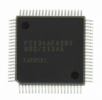
DF2134AFA20V
Description
IC H8S/2100 MCU FLASH 80QFP
Manufacturer
Renesas Electronics America
Series
H8® H8S/2100r
Datasheets
1.HEWH8E10A.pdf
(19 pages)
2.D12312SVTE25V.pdf
(341 pages)
3.DF2134AFA20V.pdf
(1063 pages)
Specifications of DF2134AFA20V
Core Processor
H8S/2000
Core Size
16-Bit
Speed
20MHz
Connectivity
IrDA, SCI
Peripherals
POR, PWM, WDT
Number Of I /o
58
Program Memory Size
128KB (128K x 8)
Program Memory Type
FLASH
Ram Size
4K x 8
Voltage - Supply (vcc/vdd)
4 V ~ 5.5 V
Data Converters
A/D 8x10b; D/A 2x8b
Oscillator Type
Internal
Operating Temperature
-20°C ~ 75°C
Package / Case
80-QFP
For Use With
3DK2166 - DEV EVAL KIT H8S/2166
Lead Free Status / RoHS Status
Lead free / RoHS Compliant
Eeprom Size
-
Available stocks
Company
Part Number
Manufacturer
Quantity
Price
Company:

Part Number:
DF2134AFA20V
Manufacturer:
Renesas Electronics America
Quantity:
10 000


7.4
An interrupt request is issued to the CPU when the DTC finishes the specified number of data
transfers, or a data transfer for which the DISEL bit was set to 1. In the case of interrupt activation,
the interrupt set as the activation source is generated. These interrupts to the CPU are subject to
CPU mask level and interrupt controller priority level control.
In the case of activation by software, a software-activated data transfer end interrupt (SWDTEND)
is generated.
When the DISEL bit is 1 and one data transfer has ended, or the specified number of transfers
have ended, after data transfer ends, the SWDTE bit is held at 1 and an SWDTEND interrupt is
generated. The interrupt handling routine should clear the SWDTE bit to 0.
When the DTC is activated by software, an SWDTEND interrupt is not generated during a data
transfer wait or during data transfer even if the SWDTE bit is set to 1.
7.5
Module Stop: When the MSTP14 bit in MSTPCR is set to 1, the DTC clock stops, and the DTC
enters the module stop state. However, 1 cannot be written in the MSTP14 bit while the DTC is
operating. When the DTC is placed in the module stop state, the DTCER registers must all be in
the cleared state when the MSTP14 bit is set to 1.
On-Chip RAM: The MRA, MRB, SAR, DAR, CRA, and CRB registers are all located in on-chip
RAM. When the DTC is used, the RAME bit in SYSCR must not be cleared to 0.
DTCE Bit Setting: For DTCE bit setting, read/write operations must be performed using bit-
manipulation instructions such as BSET and BCLR. For the initial setting only, however, when
multiple activation sources are set at one time, it is possible to disable interrupts and write after
executing a dummy read on the relevant register.
Interrupts
Usage Notes
Section 7 Data Transfer Controller [H8S/2138 Group]
Rev. 4.00 Jun 06, 2006 page 187 of 1004
REJ09B0301-0400
Related parts for DF2134AFA20V
Image
Part Number
Description
Manufacturer
Datasheet
Request
R

Part Number:
Description:
KIT STARTER FOR M16C/29
Manufacturer:
Renesas Electronics America
Datasheet:

Part Number:
Description:
KIT STARTER FOR R8C/2D
Manufacturer:
Renesas Electronics America
Datasheet:

Part Number:
Description:
R0K33062P STARTER KIT
Manufacturer:
Renesas Electronics America
Datasheet:

Part Number:
Description:
KIT STARTER FOR R8C/23 E8A
Manufacturer:
Renesas Electronics America
Datasheet:

Part Number:
Description:
KIT STARTER FOR R8C/25
Manufacturer:
Renesas Electronics America
Datasheet:

Part Number:
Description:
KIT STARTER H8S2456 SHARPE DSPLY
Manufacturer:
Renesas Electronics America
Datasheet:

Part Number:
Description:
KIT STARTER FOR R8C38C
Manufacturer:
Renesas Electronics America
Datasheet:

Part Number:
Description:
KIT STARTER FOR R8C35C
Manufacturer:
Renesas Electronics America
Datasheet:

Part Number:
Description:
KIT STARTER FOR R8CL3AC+LCD APPS
Manufacturer:
Renesas Electronics America
Datasheet:
Part Number:
Description:
KIT STARTER FOR RX610
Manufacturer:
Renesas Electronics America
Datasheet:

Part Number:
Description:
KIT STARTER FOR R32C/118
Manufacturer:
Renesas Electronics America
Datasheet:

Part Number:
Description:
KIT DEV RSK-R8C/26-29
Manufacturer:
Renesas Electronics America
Datasheet:

Part Number:
Description:
KIT STARTER FOR SH7124
Manufacturer:
Renesas Electronics America
Datasheet:

Part Number:
Description:
KIT STARTER FOR H8SX/1622
Manufacturer:
Renesas Electronics America
Datasheet:

Part Number:
Description:
KIT DEV FOR SH7203
Manufacturer:
Renesas Electronics America
Datasheet: