DF2134AFA20V Renesas Electronics America, DF2134AFA20V Datasheet - Page 52
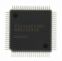
DF2134AFA20V
Manufacturer Part Number
DF2134AFA20V
Description
IC H8S/2100 MCU FLASH 80QFP
Manufacturer
Renesas Electronics America
Series
H8® H8S/2100r
Datasheets
1.HEWH8E10A.pdf
(19 pages)
2.D12312SVTE25V.pdf
(341 pages)
3.DF2134AFA20V.pdf
(1063 pages)
Specifications of DF2134AFA20V
Core Processor
H8S/2000
Core Size
16-Bit
Speed
20MHz
Connectivity
IrDA, SCI
Peripherals
POR, PWM, WDT
Number Of I /o
58
Program Memory Size
128KB (128K x 8)
Program Memory Type
FLASH
Ram Size
4K x 8
Voltage - Supply (vcc/vdd)
4 V ~ 5.5 V
Data Converters
A/D 8x10b; D/A 2x8b
Oscillator Type
Internal
Operating Temperature
-20°C ~ 75°C
Package / Case
80-QFP
For Use With
3DK2166 - DEV EVAL KIT H8S/2166
Lead Free Status / RoHS Status
Lead free / RoHS Compliant
Eeprom Size
-
Available stocks
Company
Part Number
Manufacturer
Quantity
Price
Company:

Part Number:
DF2134AFA20V
Manufacturer:
Renesas Electronics America
Quantity:
10 000


Table 17.8
Table 17.9
Table 17.10 Input Buffer Full Interrupts .................................................................................... 541
Table 17.11 HIRQ Setting/Clearing Conditions......................................................................... 541
Section 18 D/A Converter
Table 18.1
Table 18.2
Section 19 A/D Converter
Table 19.1
Table 19.2
Table 19.3
Table 19.4
Table 19.5
Section 20 RAM
Table 20.1
Section 21 ROM (Mask ROM Version, H8S/2138 F-ZTAT, H8S/2134 F-ZTAT,
Table 21.1
Table 21.2
Table 21.3
Table 21.4
Table 21.5
Table 21.6
Table 21.7
Table 21.8
Table 21.9
Table 21.10 Programmer Mode Pin Settings ............................................................................. 609
Table 21.11 Settings for Each Operating Mode in Programmer Mode ...................................... 611
Table 21.12 Programmer Mode Commands .............................................................................. 611
Table 21.13 AC Characteristics in Memory Read Mode ........................................................... 612
Table 21.14 AC Characteristics When Entering Another Mode from Memory Read Mode ..... 613
Table 21.15 AC Characteristics in Memory Read Mode ........................................................... 614
Table 21.16 AC Characteristics in Auto-Program Mode ........................................................... 615
Table 21.17 AC Characteristics in Auto-Erase Mode ................................................................ 617
Table 21.18 AC Characteristics in Status Read Mode ............................................................... 618
Table 21.19 Status Read Mode Return Commands.................................................................... 619
Rev. 4.00 Jun 06, 2006 page l of liv
and H8S/2132 F-ZTAT)
D/A Converter Registers ........................................................................................ 545
A/D Converter Pins ................................................................................................ 553
A/D Converter Registers ........................................................................................ 554
Fast A20 Gate Output Signals ................................................................................ 539
Scope of HIF Pin Shutdown in Slave Mode........................................................... 540
Input and Output Pins of D/A Converter Module .................................................. 545
Analog Input Channels and Corresponding ADDR Registers................................ 555
A/D Conversion Time (Single Mode) .................................................................... 566
Analog Pin Specifications ...................................................................................... 569
Register Configuration ........................................................................................... 574
ROM Register ........................................................................................................ 578
Operating Modes and ROM ................................................................................... 579
Flash Memory Pins................................................................................................. 586
Flash Memory Registers......................................................................................... 586
Flash Memory Erase Blocks................................................................................... 592
Setting On-Board Programming Modes................................................................. 593
System Clock Frequencies for which Automatic Adjustment of H8S/2138
or H8S/2134 Group Bit Rate Is Possible ................................................................ 596
Hardware Protection............................................................................................... 605
Software Protection ................................................................................................ 606
Related parts for DF2134AFA20V
Image
Part Number
Description
Manufacturer
Datasheet
Request
R

Part Number:
Description:
KIT STARTER FOR M16C/29
Manufacturer:
Renesas Electronics America
Datasheet:

Part Number:
Description:
KIT STARTER FOR R8C/2D
Manufacturer:
Renesas Electronics America
Datasheet:

Part Number:
Description:
R0K33062P STARTER KIT
Manufacturer:
Renesas Electronics America
Datasheet:

Part Number:
Description:
KIT STARTER FOR R8C/23 E8A
Manufacturer:
Renesas Electronics America
Datasheet:

Part Number:
Description:
KIT STARTER FOR R8C/25
Manufacturer:
Renesas Electronics America
Datasheet:

Part Number:
Description:
KIT STARTER H8S2456 SHARPE DSPLY
Manufacturer:
Renesas Electronics America
Datasheet:

Part Number:
Description:
KIT STARTER FOR R8C38C
Manufacturer:
Renesas Electronics America
Datasheet:

Part Number:
Description:
KIT STARTER FOR R8C35C
Manufacturer:
Renesas Electronics America
Datasheet:

Part Number:
Description:
KIT STARTER FOR R8CL3AC+LCD APPS
Manufacturer:
Renesas Electronics America
Datasheet:
Part Number:
Description:
KIT STARTER FOR RX610
Manufacturer:
Renesas Electronics America
Datasheet:

Part Number:
Description:
KIT STARTER FOR R32C/118
Manufacturer:
Renesas Electronics America
Datasheet:

Part Number:
Description:
KIT DEV RSK-R8C/26-29
Manufacturer:
Renesas Electronics America
Datasheet:

Part Number:
Description:
KIT STARTER FOR SH7124
Manufacturer:
Renesas Electronics America
Datasheet:

Part Number:
Description:
KIT STARTER FOR H8SX/1622
Manufacturer:
Renesas Electronics America
Datasheet:

Part Number:
Description:
KIT DEV FOR SH7203
Manufacturer:
Renesas Electronics America
Datasheet: