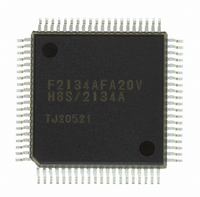
DF2134AFA20V Renesas Electronics America, DF2134AFA20V Datasheet - Page 758

DF2134AFA20V
Manufacturer Part Number
DF2134AFA20V
Description
IC H8S/2100 MCU FLASH 80QFP
Manufacturer
Renesas Electronics America
Series
H8® H8S/2100r
Datasheets
1.HEWH8E10A.pdf
(19 pages)
2.D12312SVTE25V.pdf
(341 pages)
3.DF2134AFA20V.pdf
(1063 pages)
Specifications of DF2134AFA20V
Core Processor
H8S/2000
Core Size
16-Bit
Speed
20MHz
Connectivity
IrDA, SCI
Peripherals
POR, PWM, WDT
Number Of I /o
58
Program Memory Size
128KB (128K x 8)
Program Memory Type
FLASH
Ram Size
4K x 8
Voltage - Supply (vcc/vdd)
4 V ~ 5.5 V
Data Converters
A/D 8x10b; D/A 2x8b
Oscillator Type
Internal
Operating Temperature
-20°C ~ 75°C
Package / Case
80-QFP
For Use With
3DK2166 - DEV EVAL KIT H8S/2166
Lead Free Status / RoHS Status
Lead free / RoHS Compliant
Eeprom Size
-
Available stocks
Company
Part Number
Manufacturer
Quantity
Price
Company:
Part Number:
DF2134AFA20V
Manufacturer:
Renesas Electronics America
Quantity:
10 000
- Current page: 758 of 1063
- Download datasheet (6Mb)
Section 24 Power-Down State
24.11
24.11.1 Overview of Direct Transition
There are three operating modes in which the CPU executes programs: high-speed mode, medium-
speed mode, and subactive mode. A transition between high-speed mode and subactive mode
without halting the program is called a direct transition. A direct transition can be carried out by
setting the DTON bit in LPWRCR to 1 and executing a SLEEP instruction. After the transition,
direct transition exception handling is started.
Direct Transition from High-Speed Mode to Subactive Mode: If a SLEEP instruction is
executed in high-speed mode while the SSBY bit in SBYCR, the LSON bit and DTON bit in
LPWRCR, and the PSS bit in TSCR (WDT1) are all set to 1, a transition is made to subactive
mode.
Direct Transition from Subactive Mode to High-Speed Mode: If a SLEEP instruction is
executed in subactive mode while the SSBY bit in SBYCR is set to 1, the LSON bit is cleared to 0
and the DTON bit is set to 1 in LPWRCR, and the PSS bit in TSCR (WDT1) is set to 1, after the
elapse of the time set in bits STS2 to STS0 in SBYCR, a transition is made to directly to high-
speed mode.
24.12
1. When making a transition to subactive mode or watch mode, set the DTC to enter module stop
2. The on-chip peripheral modules (DTC and TPU) which halt operation in subactive mode
Rev. 4.00 Jun 06, 2006 page 702 of 1004
REJ09B0301-0400
mode (write 1 to the relevant bits in MSTPCR), and then read the relevant bits to confirm that
they are set to 1 before mode transition. Do not clear module stop mode (write 0 to the relevant
bits in MSTPCR) until a transition from subactive mode to high-speed mode or medium-speed
mode has been performed.
If a DTC activation source occurs in sub-active mode, the DTC will be activated only after
module stop mode has been cleared and high-speed mode or medium-speed mode has been
entered.
cannot clear an interrupt in subactive mode. Therefore, if a transition is made to sub-active
mode while an interrupt is requested, the CPU interrupt source cannot be cleared. Disable the
interrupts of each on-chip peripheral module before executing a SLEEP instruction to enter
subactive mode or watch mode.
Direct Transition
Usage Notes
Related parts for DF2134AFA20V
Image
Part Number
Description
Manufacturer
Datasheet
Request
R

Part Number:
Description:
KIT STARTER FOR M16C/29
Manufacturer:
Renesas Electronics America
Datasheet:

Part Number:
Description:
KIT STARTER FOR R8C/2D
Manufacturer:
Renesas Electronics America
Datasheet:

Part Number:
Description:
R0K33062P STARTER KIT
Manufacturer:
Renesas Electronics America
Datasheet:

Part Number:
Description:
KIT STARTER FOR R8C/23 E8A
Manufacturer:
Renesas Electronics America
Datasheet:

Part Number:
Description:
KIT STARTER FOR R8C/25
Manufacturer:
Renesas Electronics America
Datasheet:

Part Number:
Description:
KIT STARTER H8S2456 SHARPE DSPLY
Manufacturer:
Renesas Electronics America
Datasheet:

Part Number:
Description:
KIT STARTER FOR R8C38C
Manufacturer:
Renesas Electronics America
Datasheet:

Part Number:
Description:
KIT STARTER FOR R8C35C
Manufacturer:
Renesas Electronics America
Datasheet:

Part Number:
Description:
KIT STARTER FOR R8CL3AC+LCD APPS
Manufacturer:
Renesas Electronics America
Datasheet:

Part Number:
Description:
KIT STARTER FOR RX610
Manufacturer:
Renesas Electronics America
Datasheet:

Part Number:
Description:
KIT STARTER FOR R32C/118
Manufacturer:
Renesas Electronics America
Datasheet:

Part Number:
Description:
KIT DEV RSK-R8C/26-29
Manufacturer:
Renesas Electronics America
Datasheet:

Part Number:
Description:
KIT STARTER FOR SH7124
Manufacturer:
Renesas Electronics America
Datasheet:

Part Number:
Description:
KIT STARTER FOR H8SX/1622
Manufacturer:
Renesas Electronics America
Datasheet:

Part Number:
Description:
KIT DEV FOR SH7203
Manufacturer:
Renesas Electronics America
Datasheet:


