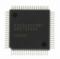
DF2134AFA20V Renesas Electronics America, DF2134AFA20V Datasheet - Page 34

DF2134AFA20V
Manufacturer Part Number
DF2134AFA20V
Description
IC H8S/2100 MCU FLASH 80QFP
Manufacturer
Renesas Electronics America
Series
H8® H8S/2100r
Datasheets
1.HEWH8E10A.pdf
(19 pages)
2.D12312SVTE25V.pdf
(341 pages)
3.DF2134AFA20V.pdf
(1063 pages)
Specifications of DF2134AFA20V
Core Processor
H8S/2000
Core Size
16-Bit
Speed
20MHz
Connectivity
IrDA, SCI
Peripherals
POR, PWM, WDT
Number Of I /o
58
Program Memory Size
128KB (128K x 8)
Program Memory Type
FLASH
Ram Size
4K x 8
Voltage - Supply (vcc/vdd)
4 V ~ 5.5 V
Data Converters
A/D 8x10b; D/A 2x8b
Oscillator Type
Internal
Operating Temperature
-20°C ~ 75°C
Package / Case
80-QFP
For Use With
3DK2166 - DEV EVAL KIT H8S/2166
Lead Free Status / RoHS Status
Lead free / RoHS Compliant
Eeprom Size
-
Available stocks
Company
Part Number
Manufacturer
Quantity
Price
Company:
Part Number:
DF2134AFA20V
Manufacturer:
Renesas Electronics America
Quantity:
10 000
- Current page: 34 of 1063
- Download datasheet (6Mb)
Section 24 Power-Down State
24.1 Overview........................................................................................................................... 681
24.2 Register Descriptions ........................................................................................................ 685
24.3 Medium-Speed Mode........................................................................................................ 691
24.4 Sleep Mode ....................................................................................................................... 692
24.5 Module Stop Mode ........................................................................................................... 693
24.6 Software Standby Mode.................................................................................................... 695
24.7 Hardware Standby Mode .................................................................................................. 697
24.8 Watch Mode...................................................................................................................... 699
24.9 Subsleep Mode.................................................................................................................. 700
24.10 Subactive Mode ................................................................................................................ 701
24.11 Direct Transition ............................................................................................................... 702
24.12 Usage Notes ...................................................................................................................... 702
Section 25 Electrical Characteristics
25.1 Voltage of Power Supply and Operating Range ............................................................... 703
25.2 Electrical Characteristics of H8S/2138 F-ZTAT............................................................... 706
Rev. 4.00 Jun 06, 2006 page xxxii of liv
24.1.1 Register Configuration......................................................................................... 685
24.2.1 Standby Control Register (SBYCR) .................................................................... 685
24.2.2 Low-Power Control Register (LPWRCR) ........................................................... 687
24.2.3 Timer Control/Status Register (TCSR) ................................................................ 689
24.2.4 Module Stop Control Register (MSTPCR) .......................................................... 690
24.4.1 Sleep Mode .......................................................................................................... 692
24.4.2 Clearing Sleep Mode............................................................................................ 692
24.5.1 Module Stop Mode .............................................................................................. 693
24.5.2 Usage Note........................................................................................................... 694
24.6.1 Software Standby Mode....................................................................................... 695
24.6.2 Clearing Software Standby Mode ........................................................................ 695
24.6.3 Setting Oscillation Settling Time after Clearing Software Standby Mode .......... 696
24.6.4 Software Standby Mode Application Example.................................................... 696
24.6.5 Usage Note........................................................................................................... 697
24.7.1 Hardware Standby Mode ..................................................................................... 697
24.7.2 Hardware Standby Mode Timing......................................................................... 698
24.8.1 Watch Mode......................................................................................................... 699
24.8.2 Clearing Watch Mode .......................................................................................... 699
24.9.1 Subsleep Mode..................................................................................................... 700
24.9.2 Clearing Subsleep Mode ...................................................................................... 700
24.10.1 Subactive Mode ................................................................................................... 701
24.10.2 Clearing Subactive Mode..................................................................................... 701
24.11.1 Overview of Direct Transition ............................................................................. 702
25.2.1 Absolute Maximum Ratings ................................................................................ 706
......................................................................................... 681
.............................................................................. 703
Related parts for DF2134AFA20V
Image
Part Number
Description
Manufacturer
Datasheet
Request
R

Part Number:
Description:
KIT STARTER FOR M16C/29
Manufacturer:
Renesas Electronics America
Datasheet:

Part Number:
Description:
KIT STARTER FOR R8C/2D
Manufacturer:
Renesas Electronics America
Datasheet:

Part Number:
Description:
R0K33062P STARTER KIT
Manufacturer:
Renesas Electronics America
Datasheet:

Part Number:
Description:
KIT STARTER FOR R8C/23 E8A
Manufacturer:
Renesas Electronics America
Datasheet:

Part Number:
Description:
KIT STARTER FOR R8C/25
Manufacturer:
Renesas Electronics America
Datasheet:

Part Number:
Description:
KIT STARTER H8S2456 SHARPE DSPLY
Manufacturer:
Renesas Electronics America
Datasheet:

Part Number:
Description:
KIT STARTER FOR R8C38C
Manufacturer:
Renesas Electronics America
Datasheet:

Part Number:
Description:
KIT STARTER FOR R8C35C
Manufacturer:
Renesas Electronics America
Datasheet:

Part Number:
Description:
KIT STARTER FOR R8CL3AC+LCD APPS
Manufacturer:
Renesas Electronics America
Datasheet:

Part Number:
Description:
KIT STARTER FOR RX610
Manufacturer:
Renesas Electronics America
Datasheet:

Part Number:
Description:
KIT STARTER FOR R32C/118
Manufacturer:
Renesas Electronics America
Datasheet:

Part Number:
Description:
KIT DEV RSK-R8C/26-29
Manufacturer:
Renesas Electronics America
Datasheet:

Part Number:
Description:
KIT STARTER FOR SH7124
Manufacturer:
Renesas Electronics America
Datasheet:

Part Number:
Description:
KIT STARTER FOR H8SX/1622
Manufacturer:
Renesas Electronics America
Datasheet:

Part Number:
Description:
KIT DEV FOR SH7203
Manufacturer:
Renesas Electronics America
Datasheet:


