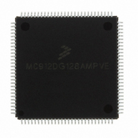
MC912DG128AMPVE Freescale Semiconductor, MC912DG128AMPVE Datasheet - Page 320

MC912DG128AMPVE
Manufacturer Part Number
MC912DG128AMPVE
Description
IC MCU 128K FLASH 8MHZ 112-LQFP
Manufacturer
Freescale Semiconductor
Series
HC12r
Datasheet
1.MC912DG128ACPVER.pdf
(478 pages)
Specifications of MC912DG128AMPVE
Core Processor
CPU12
Core Size
16-Bit
Speed
8MHz
Connectivity
CAN, I²C, SCI, SPI
Peripherals
POR, PWM, WDT
Number Of I /o
69
Program Memory Size
128KB (128K x 8)
Program Memory Type
FLASH
Eeprom Size
2K x 8
Ram Size
8K x 8
Voltage - Supply (vcc/vdd)
4.5 V ~ 5.5 V
Data Converters
A/D 16x8/10b
Oscillator Type
Internal
Operating Temperature
-40°C ~ 125°C
Package / Case
112-LQFP
Processor Series
HC912D
Core
HC12
Data Bus Width
16 bit
Data Ram Size
8 KB
Interface Type
CAN/I2C/SCI/SPI
Maximum Clock Frequency
8 MHz
Number Of Programmable I/os
69
Number Of Timers
8
Maximum Operating Temperature
+ 125 C
Mounting Style
SMD/SMT
3rd Party Development Tools
EWHCS12
Minimum Operating Temperature
- 40 C
On-chip Adc
2 (8-ch x 10-bit)
Lead Free Status / RoHS Status
Lead free / RoHS Compliant
Available stocks
Company
Part Number
Manufacturer
Quantity
Price
Company:
Part Number:
MC912DG128AMPVE
Manufacturer:
FREESCALE
Quantity:
2 902
Company:
Part Number:
MC912DG128AMPVE
Manufacturer:
Freescale Semiconductor
Quantity:
10 000
- Current page: 320 of 478
- Download datasheet (4Mb)
Inter IC Bus
17.7.4 Generation of STOP
Technical Data
320
ISR
TRANSMIT
monitor the IBIF bit rather than the TCF bit since their operation is
different when arbitration is lost.
Note that when an interrupt occurs at the end of the address cycle the
master will always be in transmit mode, i.e. the address is transmitted. If
master receive mode is required, indicated by R/W bit in IBDR, then the
Tx/Rx bit should be toggled at this stage.
During slave mode address cycles (IAAS=1) the SRW bit in the status
register is read to determine the direction of the subsequent transfer and
the Tx/Rx bit is programmed accordingly. For slave mode data cycles
(IAAS=0) the SRW bit is not valid, the Tx/Rx bit in the control register
should be read to determine the direction of the current transfer.
The following is an example of a software response by a 'master
transmitter' in the interrupt routine (see
A data transfer ends with a STOP signal generated by the 'master'
device. A master transmitter can simply generate a STOP signal after all
the data has been transmitted. The following is an example showing how
a stop condition is generated by a master transmitter.
If a master receiver wants to terminate a data transfer, it must inform the
slave transmitter by not acknowledging the last byte of data which can
MASTX
END
EMASTX
Freescale Semiconductor, Inc.
BCLR
BRCLR
BRCLR
BRSET
MOVB
For More Information On This Product,
TST
BEQ
BRSET
MOVB
DEC
BRA
BCLR
RTI
Go to: www.freescale.com
IBSR,#$02
IBCR,#$20,SLAVE
IBCR,#$10,RECEIVE
IBSR,#$01,END
DATABUF,IBDR
Inter IC Bus
TXCNT
END
IBSR,#$01,END
DATABUF,IBDR
TXCNT
EMASTX
IBCR,#$20
;CLEAR THE IBIF FLAG
;BRANCH IF IN SLAVE MODE
;BRANCH IF IN RECEIVE MODE
;IF NO ACK, END OF TRANSMISSION
;TRANSMIT NEXT BYTE OF DATA
;GET VALUE FROM THE
;TRANSMITING COUNTER
;END IF NO MORE DATA
;END IF NO ACK
;TRANSMIT NEXT BYTE OF DATA
;DECREASE THE TXCNT
;EXIT
;GENERATE A STOP CONDITION
;RETURN FROM INTERRUPT
Figure
MC68HC912DT128A — Rev 4.0
17-4).
MOTOROLA
Related parts for MC912DG128AMPVE
Image
Part Number
Description
Manufacturer
Datasheet
Request
R
Part Number:
Description:
Manufacturer:
Freescale Semiconductor, Inc
Datasheet:
Part Number:
Description:
Manufacturer:
Freescale Semiconductor, Inc
Datasheet:
Part Number:
Description:
Manufacturer:
Freescale Semiconductor, Inc
Datasheet:
Part Number:
Description:
Manufacturer:
Freescale Semiconductor, Inc
Datasheet:
Part Number:
Description:
Manufacturer:
Freescale Semiconductor, Inc
Datasheet:
Part Number:
Description:
Manufacturer:
Freescale Semiconductor, Inc
Datasheet:
Part Number:
Description:
Manufacturer:
Freescale Semiconductor, Inc
Datasheet:
Part Number:
Description:
Manufacturer:
Freescale Semiconductor, Inc
Datasheet:
Part Number:
Description:
Manufacturer:
Freescale Semiconductor, Inc
Datasheet:
Part Number:
Description:
Manufacturer:
Freescale Semiconductor, Inc
Datasheet:
Part Number:
Description:
Manufacturer:
Freescale Semiconductor, Inc
Datasheet:
Part Number:
Description:
Manufacturer:
Freescale Semiconductor, Inc
Datasheet:
Part Number:
Description:
Manufacturer:
Freescale Semiconductor, Inc
Datasheet:
Part Number:
Description:
Manufacturer:
Freescale Semiconductor, Inc
Datasheet:
Part Number:
Description:
Manufacturer:
Freescale Semiconductor, Inc
Datasheet:


