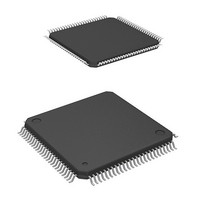
DF2239TF16I Renesas Electronics America, DF2239TF16I Datasheet - Page 28

DF2239TF16I
Manufacturer Part Number
DF2239TF16I
Description
MCU 3V 384K I-TEMP 100-TQFP
Manufacturer
Renesas Electronics America
Series
H8® H8S/2200r
Datasheet
1.DF2238RFA6V.pdf
(1048 pages)
Specifications of DF2239TF16I
Core Processor
H8S/2000
Core Size
16-Bit
Speed
16MHz
Connectivity
I²C, SCI, SmartCard
Peripherals
DMA, POR, PWM, WDT
Number Of I /o
72
Program Memory Size
384KB (384K x 8)
Program Memory Type
FLASH
Ram Size
32K x 8
Voltage - Supply (vcc/vdd)
2.7 V ~ 3.6 V
Data Converters
A/D 8x10b; D/A 2x8b
Oscillator Type
Internal
Operating Temperature
-40°C ~ 85°C
Package / Case
100-TQFP, 100-VQFP
Lead Free Status / RoHS Status
Contains lead / RoHS non-compliant
Eeprom Size
-
Other names
HD64F2239TF16I
HD64F2239TF16I
HD64F2239TF16I
- Current page: 28 of 1048
- Download datasheet (6Mb)
Section 9 Data Transfer Controller (DTC) ........................................................281
9.1
9.2
9.3
9.4
9.5
9.6
9.7
9.8
Section 10 I/O Ports...........................................................................................305
10.1 Port 1................................................................................................................................. 309
Rev. 6.00 Mar. 18, 2010 Page xxvi of lx
REJ09B0054-0600
8.7.3
8.7.4
8.7.5
8.7.6
8.7.7
Features............................................................................................................................. 281
Register Descriptions ........................................................................................................ 282
9.2.1
9.2.2
9.2.3
9.2.4
9.2.5
9.2.6
9.2.7
9.2.8
Activation Sources ............................................................................................................ 288
Location of Register Information and DTC Vector Table ................................................ 289
Operation .......................................................................................................................... 293
9.5.1
9.5.2
9.5.3
9.5.4
9.5.5
9.5.6
9.5.7
Procedures for Using DTC................................................................................................ 301
9.6.1
9.6.2
Examples of Use of the DTC ............................................................................................ 302
9.7.1
9.7.2
Usage Notes ...................................................................................................................... 303
9.8.1
9.8.2
9.8.3
Medium-Speed Mode........................................................................................... 277
Activation by Falling Edge on DREQ Pin ........................................................... 278
Activation Source Acceptance............................................................................. 278
Internal Interrupt after End of Transfer................................................................ 278
Channel Re-Setting .............................................................................................. 279
DTC Mode Register A (MRA) ............................................................................ 283
DTC Mode Register B (MRB)............................................................................. 284
DTC Source Address Register (SAR).................................................................. 285
DTC Destination Address Register (DAR).......................................................... 285
DTC Transfer Count Register A (CRA) .............................................................. 285
DTC Transfer Count Register B (CRB)............................................................... 285
DTC Enable Registers A to G, and I (DTCERA to DTCERG, and DTCERI) .... 286
DTC Vector Register (DTVECR)........................................................................ 287
Normal Mode....................................................................................................... 294
Repeat Mode ........................................................................................................ 294
Block Transfer Mode ........................................................................................... 295
Chain Transfer ..................................................................................................... 297
Interrupts.............................................................................................................. 298
Operation Timing................................................................................................. 298
Number of DTC Execution States ....................................................................... 300
Activation by Interrupt......................................................................................... 301
Activation by Software ........................................................................................ 301
Normal Mode....................................................................................................... 302
Software Activation ............................................................................................. 302
Module Stop Mode Setting .................................................................................. 303
On-Chip RAM ..................................................................................................... 303
DTCE Bit Setting................................................................................................. 303
Related parts for DF2239TF16I
Image
Part Number
Description
Manufacturer
Datasheet
Request
R

Part Number:
Description:
CONN SOCKET 2POS 7.92MM WHITE
Manufacturer:
Hirose Electric Co Ltd
Datasheet:

Part Number:
Description:
CONN SOCKET 4POS 7.92MM WHITE
Manufacturer:
Hirose Electric Co Ltd
Datasheet:

Part Number:
Description:
CONN SOCKET 5POS 7.92MM WHITE
Manufacturer:
Hirose Electric Co Ltd
Datasheet:

Part Number:
Description:
CONN SOCKET 3POS 7.92MM WHITE
Manufacturer:
Hirose Electric Co Ltd
Datasheet:

Part Number:
Description:
CONN SOCKET 5POS 7.92MM WHITE
Manufacturer:
Hirose Electric Co Ltd
Datasheet:

Part Number:
Description:
CONN SOCKET 2POS 7.92MM WHITE
Manufacturer:
Hirose Electric Co Ltd
Datasheet:

Part Number:
Description:
CONN SOCKET 3POS 7.92MM WHITE
Manufacturer:
Hirose Electric Co Ltd
Datasheet:

Part Number:
Description:
CONN SOCKET 4POS 7.92MM WHITE
Manufacturer:
Hirose Electric Co Ltd
Datasheet:

Part Number:
Description:
CONN HEADER 2POS 7.92MM R/A TIN
Manufacturer:
Hirose Electric Co Ltd
Datasheet:

Part Number:
Description:
CONN HEADER 4POS 7.92MM R/A TIN
Manufacturer:
Hirose Electric Co Ltd
Datasheet:

Part Number:
Description:
KIT STARTER FOR M16C/29
Manufacturer:
Renesas Electronics America
Datasheet:

Part Number:
Description:
KIT STARTER FOR R8C/2D
Manufacturer:
Renesas Electronics America
Datasheet:

Part Number:
Description:
R0K33062P STARTER KIT
Manufacturer:
Renesas Electronics America
Datasheet:

Part Number:
Description:
KIT STARTER FOR R8C/23 E8A
Manufacturer:
Renesas Electronics America
Datasheet:

Part Number:
Description:
KIT STARTER FOR R8C/25
Manufacturer:
Renesas Electronics America
Datasheet:


