ATEVK1105 Atmel, ATEVK1105 Datasheet - Page 100
ATEVK1105
Manufacturer Part Number
ATEVK1105
Description
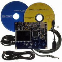
KIT EVAL FOR AT32UC3A0
Manufacturer
Atmel
Series
AVR®32r
Type
MCUr
Datasheets
1.ATAVRONE-PROBECBL.pdf
(16 pages)
2.ATEVK1104.pdf
(826 pages)
3.ATEVK1105.pdf
(28 pages)
Specifications of ATEVK1105
Contents
Evaluation Board, Software and Documentation
Processor To Be Evaluated
AT32UC3A0512
Processor Series
AVR
Data Bus Width
32 bit
Interface Type
USART, TWI, USB, SPI, Ethernet
Operating Supply Voltage
3.3 V
Silicon Manufacturer
Atmel
Core Architecture
AVR
Core Sub-architecture
AVR UC3
Silicon Core Number
AT32UC3A0512
Silicon Family Name
AVR
Kit Contents
Board CD Docs
Rohs Compliant
Yes
For Use With/related Products
AT32UC3A0
Lead Free Status / RoHS Status
Lead free / RoHS Compliant


16.3.1
16.3.2
16.3.3
32058J–AVR32–04/11
Non maskable interrupts
CPU response
Clearing an interrupt request
oritize between them. All of the input lines in each group are logically-ORed together to form the
GrpReqN lines, indicating if there is a pending interrupt in the corresponding group.
The Request Masking hardware maps each of the GrpReq lines to a priority level from INT0 to
INT3 by associating each group with the INTLEVEL field in the corresponding IPR register. The
GrpReq inputs are then masked by the I0M, I1M, I2M, I3M and GM mask bits from the CPU sta-
tus register. Any interrupt group that has a pending interrupt of a priority level that is not masked
by the CPU status register, gets its corresponding ValReq line asserted.
The Prioritizer hardware uses the ValReq lines and the INTLEVEL field in the IPRs to select the
pending interrupt of the highest priority. If a NMI interrupt is pending, it automatically gets high-
est priority of any pending interrupt. If several interrupt groups of the highest pending interrupt
level have pending interrupts, the interrupt group with the highest number is selected.
Interrupt level (INTLEVEL) and handler autovector offset (AUTOVECTOR) of the selected inter-
rupt are transmitted to the CPU for interrupt handling and context switching. The CPU doesn't
need to know which interrupt is requesting handling, but only the level and the offset of the han-
dler address. The IRR registers contain the interrupt request lines of the groups and can be read
via PB for checking which interrupts of the group are actually active.
Masking of the interrupt requests is done based on five interrupt mask bits of the CPU status
register, namely interrupt level 3 mask (I3M) to interrupt level 0 mask (I0M), and Global interrupt
mask (GM). An interrupt request is masked if either the Global interrupt mask or the correspond-
ing interrupt level mask bit is set.
A NMI request has priority over all other interrupt requests. NMI has a dedicated exception vec-
tor address defined by the AVR32 architecture, so AUTOVECTOR is undefined when
INTLEVEL indicates that an NMI is pending.
When the CPU receives an interrupt request it checks if any other exceptions are pending. If no
exceptions of higher priority are pending, interrupt handling is initiated. When initiating interrupt
handling, the corresponding interrupt mask bit is set automatically for this and lower levels in sta-
tus register. E.g, if interrupt on level 3 is approved for handling the interrupt mask bits I3M, I2M,
I1M, and I0M are set in status register. If interrupt on level 1 is approved the masking bits I1M,
and I0M are set in status register. The handler offset is calculated from AUTOVECTOR and
EVBA and a change-of-flow to this address is performed.
Setting of the interrupt mask bits prevents the interrupts from the same and lower levels to be
passed trough the interrupt controller. Setting of the same level mask bit prevents also multiple
request of the same interrupt to happen.
It is the responsibility of the handler software to clear the interrupt request that caused the inter-
rupt before returning from the interrupt handler. If the conditions that caused the interrupt are not
cleared, the interrupt request remains active.
Clearing of the interrupt request is done by writing to registers in the corresponding peripheral
module, which then clears the corresponding NMIREQ/IREQ signal.
The recommended way of clearing an interrupt request is a store operation to the controlling
peripheral register, followed by a dummy load operation from the same register. This causes a
AT32UC3A
100
Related parts for ATEVK1105
Image
Part Number
Description
Manufacturer
Datasheet
Request
R

Part Number:
Description:
DEV KIT FOR AVR/AVR32
Manufacturer:
Atmel
Datasheet:

Part Number:
Description:
INTERVAL AND WIPE/WASH WIPER CONTROL IC WITH DELAY
Manufacturer:
ATMEL Corporation
Datasheet:
Part Number:
Description:
Low-Voltage Voice-Switched IC for Hands-Free Operation
Manufacturer:
ATMEL Corporation
Datasheet:
Part Number:
Description:
MONOLITHIC INTEGRATED FEATUREPHONE CIRCUIT
Manufacturer:
ATMEL Corporation
Datasheet:
Part Number:
Description:
AM-FM Receiver IC U4255BM-M
Manufacturer:
ATMEL Corporation
Datasheet:
Part Number:
Description:
Monolithic Integrated Feature Phone Circuit
Manufacturer:
ATMEL Corporation
Datasheet:
Part Number:
Description:
Multistandard Video-IF and Quasi Parallel Sound Processing
Manufacturer:
ATMEL Corporation
Datasheet:
Part Number:
Description:
High-performance EE PLD
Manufacturer:
ATMEL Corporation
Datasheet:
Part Number:
Description:
8-bit Flash Microcontroller
Manufacturer:
ATMEL Corporation
Datasheet:
Part Number:
Description:
2-Wire Serial EEPROM
Manufacturer:
ATMEL Corporation
Datasheet: