ATEVK1105 Atmel, ATEVK1105 Datasheet - Page 132
ATEVK1105
Manufacturer Part Number
ATEVK1105
Description
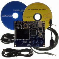
KIT EVAL FOR AT32UC3A0
Manufacturer
Atmel
Series
AVR®32r
Type
MCUr
Datasheets
1.ATAVRONE-PROBECBL.pdf
(16 pages)
2.ATEVK1104.pdf
(826 pages)
3.ATEVK1105.pdf
(28 pages)
Specifications of ATEVK1105
Contents
Evaluation Board, Software and Documentation
Processor To Be Evaluated
AT32UC3A0512
Processor Series
AVR
Data Bus Width
32 bit
Interface Type
USART, TWI, USB, SPI, Ethernet
Operating Supply Voltage
3.3 V
Silicon Manufacturer
Atmel
Core Architecture
AVR
Core Sub-architecture
AVR UC3
Silicon Core Number
AT32UC3A0512
Silicon Family Name
AVR
Kit Contents
Board CD Docs
Rohs Compliant
Yes
For Use With/related Products
AT32UC3A0
Lead Free Status / RoHS Status
Lead free / RoHS Compliant


19. HSB Bus Matrix (HMATRIX)
19.1
19.2
19.3
19.4
32058J–AVR32–04/11
Features
Description
Memory Mapping
Special Bus Granting Mechanism
Rev: 2.3.0.1
•
•
•
•
•
•
•
•
•
•
•
The Bus Matrix implements a multi-layer bus structure, that enables parallel access paths
between multiple High Speed Bus (HSB) masters and slaves in a system, thus increasing the
overall bandwidth. The Bus Matrix interconnects up to 16 HSB Masters to up to 16 HSB Slaves.
The normal latency to connect a master to a slave is one cycle except for the default master of
the accessed slave which is connected directly (zero cycle latency). The Bus Matrix provides 16
Special Function Registers (SFR) that allow the Bus Matrix to support application specific
features.
The Bus Matrix provides one decoder for every HSB Master Interface. The decoder offers each
HSB Master several memory mappings. In fact, depending on the product, each memory area
may be assigned to several slaves. Booting at the same address while using different HSB
slaves (i.e. external RAM, internal ROM or internal Flash, etc.) becomes possible.
The Bus Matrix user interface provides Master Remap Control Register (MRCR) that performs
remap action for every master independently.
The Bus Matrix provides some speculative bus granting techniques in order to anticipate access
requests from some masters. This mechanism reduces latency at first access of a burst or single
transfer. This bus granting mechanism sets a different default master for every slave.
At the end of the current access, if no other request is pending, the slave remains connected to
its associated default master. A slave can be associated with three kinds of default masters: no
default master, last access master and fixed default master.
User Interface on peripheral bus
Configurable Number of Masters (Up to sixteen)
Configurable Number of Slaves (Up to sixteen)
One Decoder for Each Master
Three Different Memory Mappings for Each Master (Internal and External boot, Remap)
One Remap Function for Each Master
Programmable Arbitration for Each Slave
Programmable Default Master for Each Slave
One Cycle Latency for the First Access of a Burst
Zero Cycle Latency for Default Master
One Special Function Register for Each Slave (Not dedicated)
– Round-Robin
– Fixed Priority
– No Default Master
– Last Accessed Default Master
– Fixed Default Master
AT32UC3A
132
Related parts for ATEVK1105
Image
Part Number
Description
Manufacturer
Datasheet
Request
R

Part Number:
Description:
DEV KIT FOR AVR/AVR32
Manufacturer:
Atmel
Datasheet:

Part Number:
Description:
INTERVAL AND WIPE/WASH WIPER CONTROL IC WITH DELAY
Manufacturer:
ATMEL Corporation
Datasheet:
Part Number:
Description:
Low-Voltage Voice-Switched IC for Hands-Free Operation
Manufacturer:
ATMEL Corporation
Datasheet:
Part Number:
Description:
MONOLITHIC INTEGRATED FEATUREPHONE CIRCUIT
Manufacturer:
ATMEL Corporation
Datasheet:
Part Number:
Description:
AM-FM Receiver IC U4255BM-M
Manufacturer:
ATMEL Corporation
Datasheet:
Part Number:
Description:
Monolithic Integrated Feature Phone Circuit
Manufacturer:
ATMEL Corporation
Datasheet:
Part Number:
Description:
Multistandard Video-IF and Quasi Parallel Sound Processing
Manufacturer:
ATMEL Corporation
Datasheet:
Part Number:
Description:
High-performance EE PLD
Manufacturer:
ATMEL Corporation
Datasheet:
Part Number:
Description:
8-bit Flash Microcontroller
Manufacturer:
ATMEL Corporation
Datasheet:
Part Number:
Description:
2-Wire Serial EEPROM
Manufacturer:
ATMEL Corporation
Datasheet: