ATEVK1105 Atmel, ATEVK1105 Datasheet - Page 510
ATEVK1105
Manufacturer Part Number
ATEVK1105
Description
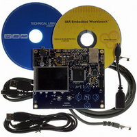
KIT EVAL FOR AT32UC3A0
Manufacturer
Atmel
Series
AVR®32r
Type
MCUr
Datasheets
1.ATAVRONE-PROBECBL.pdf
(16 pages)
2.ATEVK1104.pdf
(826 pages)
3.ATEVK1105.pdf
(28 pages)
Specifications of ATEVK1105
Contents
Evaluation Board, Software and Documentation
Processor To Be Evaluated
AT32UC3A0512
Processor Series
AVR
Data Bus Width
32 bit
Interface Type
USART, TWI, USB, SPI, Ethernet
Operating Supply Voltage
3.3 V
Silicon Manufacturer
Atmel
Core Architecture
AVR
Core Sub-architecture
AVR UC3
Silicon Core Number
AT32UC3A0512
Silicon Family Name
AVR
Kit Contents
Board CD Docs
Rohs Compliant
Yes
For Use With/related Products
AT32UC3A0
Lead Free Status / RoHS Status
Lead free / RoHS Compliant


30.7.1.10
Figure 30-12. ID Detection Input Block Diagram
32058J–AVR32–04/11
ID Detection
USB_ID
In host mode, the VBUS bit follows an hysteresis based on Session_valid and Va_Vbus_valid:
The VBus Transition interrupt (VBUSTI) is raised on each transition of the VBUS bit.
The VBUS bit is effective whether the USB macro is enabled or not.
Figure 30-12
The USB mode (device or host) can be either detected from the USB_ID pin or software
selected from the UIMOD bit, according to the UIDE bit. This allows the USB_ID pin to be used
as a general purpose I/O pin even when the USB interface is enabled.
By default, the USB_ID pin is selected (UIDE = 1) and the USB macro is in device mode (ID = 1),
what corresponds to the case where no Mini-A plug is connected, i.e. no plug or a Mini-B plug is
connected and the USB_ID pin is kept high by the internal pull-up resistor from the GPIO con-
troller (which must be enabled if USB_ID is used).
The ID Transition interrupt (IDTI) is raised on each transition of the ID bit, i.e. when a Mini-A plug
(host mode) is connected or disconnected. This does not occur when a Mini-B plug (device
mode) is connected or disconnected.
The ID bit is effective whether the USB macro is enabled or not.
•it is cleared when the voltage on the VBUS pad is lower than 1.4 V.
•it is set when the voltage on the VBUS pad is higher than or equal to 4.4 V;
•it is cleared when the voltage on the VBUS pad is lower than 1.4 V.
GPIO Controller
VDD
shows how the ID transitions are detected.
UIMOD
USBCON
USBCON
1
0
UIDE
USBSTA
ID
USBSTA
IDTI
AT32UC3A
510
Related parts for ATEVK1105
Image
Part Number
Description
Manufacturer
Datasheet
Request
R

Part Number:
Description:
DEV KIT FOR AVR/AVR32
Manufacturer:
Atmel
Datasheet:

Part Number:
Description:
INTERVAL AND WIPE/WASH WIPER CONTROL IC WITH DELAY
Manufacturer:
ATMEL Corporation
Datasheet:
Part Number:
Description:
Low-Voltage Voice-Switched IC for Hands-Free Operation
Manufacturer:
ATMEL Corporation
Datasheet:
Part Number:
Description:
MONOLITHIC INTEGRATED FEATUREPHONE CIRCUIT
Manufacturer:
ATMEL Corporation
Datasheet:
Part Number:
Description:
AM-FM Receiver IC U4255BM-M
Manufacturer:
ATMEL Corporation
Datasheet:
Part Number:
Description:
Monolithic Integrated Feature Phone Circuit
Manufacturer:
ATMEL Corporation
Datasheet:
Part Number:
Description:
Multistandard Video-IF and Quasi Parallel Sound Processing
Manufacturer:
ATMEL Corporation
Datasheet:
Part Number:
Description:
High-performance EE PLD
Manufacturer:
ATMEL Corporation
Datasheet:
Part Number:
Description:
8-bit Flash Microcontroller
Manufacturer:
ATMEL Corporation
Datasheet:
Part Number:
Description:
2-Wire Serial EEPROM
Manufacturer:
ATMEL Corporation
Datasheet: