ATEVK1105 Atmel, ATEVK1105 Datasheet - Page 322
ATEVK1105
Manufacturer Part Number
ATEVK1105
Description
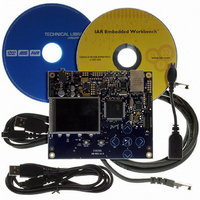
KIT EVAL FOR AT32UC3A0
Manufacturer
Atmel
Series
AVR®32r
Type
MCUr
Datasheets
1.ATAVRONE-PROBECBL.pdf
(16 pages)
2.ATEVK1104.pdf
(826 pages)
3.ATEVK1105.pdf
(28 pages)
Specifications of ATEVK1105
Contents
Evaluation Board, Software and Documentation
Processor To Be Evaluated
AT32UC3A0512
Processor Series
AVR
Data Bus Width
32 bit
Interface Type
USART, TWI, USB, SPI, Ethernet
Operating Supply Voltage
3.3 V
Silicon Manufacturer
Atmel
Core Architecture
AVR
Core Sub-architecture
AVR UC3
Silicon Core Number
AT32UC3A0512
Silicon Family Name
AVR
Kit Contents
Board CD Docs
Rohs Compliant
Yes
For Use With/related Products
AT32UC3A0
Lead Free Status / RoHS Status
Lead free / RoHS Compliant


Figure 26-23. Timeguard Operations
26.7.4.5
32058J–AVR32–04/11
Baud Rate
TXEMPTY
US_THR
TXRDY
Clock
Write
TXD
Receiver Time-out
Start
Bit
D0
D1
Table 26-7 on page 322
can handle in relation to the function of the Baud Rate.
Table 26-7.
The Receiver Time-out provides support in handling variable-length frames. This feature detects
an idle condition on the RXD line. When a time-out is detected, the bit TIMEOUT in the Channel
Status Register (CSR) rises and can generate an interrupt, thus indicating to the driver an end of
frame.
The time-out delay period (during which the receiver waits for a new character) is programmed
in the TO field of the Receiver Time-out Register (RTOR). If the TO field is programmed at 0, the
Receiver Time-out is disabled and no time-out is detected. The TIMEOUT bit in CSR remains at
0. Otherwise, the receiver loads a 16-bit counter with the value programmed in TO. This counter
is decremented at each bit period and reloaded each time a new character is received. If the
counter reaches 0, the TIMEOUT bit in the Status Register rises. Then, the user can either:
• Stop the counter clock until a new character is received. This is performed by writing the
D2
Control Register (CR) with the STTTO (Start Time-out) bit at 1. In this case, the idle state on
RXD before a new character is received will not provide a time-out. This prevents having to
D3
D4
D5
Baud Rate
115200
Bit/sec
14400
19200
28800
33400
56000
57600
1 200
9 600
D6
Maximum Timeguard Length Depending on Baud Rate
D7
Parity
Bit
Stop
Bit
indicates the maximum length of a timeguard period that the transmitter
TG = 4
Start
Bit
D0
Bit time
34.7
29.9
17.9
17.4
69.4
52.1
833
104
8.7
µs
D1
D2
D3
D4
D5
D6
D7
Parity
Bit
Stop
Bit
Timeguard
AT32UC3A
212.50
26.56
17.71
13.28
8.85
7.63
4.55
4.43
2.21
ms
TG = 4
322
Related parts for ATEVK1105
Image
Part Number
Description
Manufacturer
Datasheet
Request
R

Part Number:
Description:
DEV KIT FOR AVR/AVR32
Manufacturer:
Atmel
Datasheet:

Part Number:
Description:
INTERVAL AND WIPE/WASH WIPER CONTROL IC WITH DELAY
Manufacturer:
ATMEL Corporation
Datasheet:
Part Number:
Description:
Low-Voltage Voice-Switched IC for Hands-Free Operation
Manufacturer:
ATMEL Corporation
Datasheet:
Part Number:
Description:
MONOLITHIC INTEGRATED FEATUREPHONE CIRCUIT
Manufacturer:
ATMEL Corporation
Datasheet:
Part Number:
Description:
AM-FM Receiver IC U4255BM-M
Manufacturer:
ATMEL Corporation
Datasheet:
Part Number:
Description:
Monolithic Integrated Feature Phone Circuit
Manufacturer:
ATMEL Corporation
Datasheet:
Part Number:
Description:
Multistandard Video-IF and Quasi Parallel Sound Processing
Manufacturer:
ATMEL Corporation
Datasheet:
Part Number:
Description:
High-performance EE PLD
Manufacturer:
ATMEL Corporation
Datasheet:
Part Number:
Description:
8-bit Flash Microcontroller
Manufacturer:
ATMEL Corporation
Datasheet:
Part Number:
Description:
2-Wire Serial EEPROM
Manufacturer:
ATMEL Corporation
Datasheet: