ATEVK1105 Atmel, ATEVK1105 Datasheet - Page 155
ATEVK1105
Manufacturer Part Number
ATEVK1105
Description
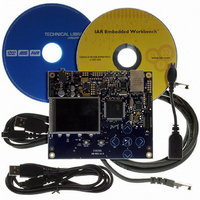
KIT EVAL FOR AT32UC3A0
Manufacturer
Atmel
Series
AVR®32r
Type
MCUr
Datasheets
1.ATAVRONE-PROBECBL.pdf
(16 pages)
2.ATEVK1104.pdf
(826 pages)
3.ATEVK1105.pdf
(28 pages)
Specifications of ATEVK1105
Contents
Evaluation Board, Software and Documentation
Processor To Be Evaluated
AT32UC3A0512
Processor Series
AVR
Data Bus Width
32 bit
Interface Type
USART, TWI, USB, SPI, Ethernet
Operating Supply Voltage
3.3 V
Silicon Manufacturer
Atmel
Core Architecture
AVR
Core Sub-architecture
AVR UC3
Silicon Core Number
AT32UC3A0512
Silicon Family Name
AVR
Kit Contents
Board CD Docs
Rohs Compliant
Yes
For Use With/related Products
AT32UC3A0
Lead Free Status / RoHS Status
Lead free / RoHS Compliant


21.4.3
21.4.4
21.4.5
21.4.6
21.4.7
21.4.8
32058J–AVR32–04/11
Transfer Counter
Reload Registers
Peripheral Selection
Transfer Size
Enabling and Disabling
Interrupts
transfer. The address will be increased by either 1, 2 or 4 depending on the size of the DMA
transfer (Byte, Half-Word or Word). The Memory Address Register can be read at any time dur-
ing transfer.
Each channel has a 16-bit Transfer Counter Register (TCR). This register must be programmed
with the number of transferred to be performed. TCR should contain the number of data items to
be transferred independently of the transfer size. The Transfer Counter Register can be read at
any time during transfer to see the number of remaining transfers.
Both the Memory Address Register and the Transfer Counter Register have a reload register,
respectively Memory Address Reload Register (MARR) and Transfer Counter Reload Register
(TCRR). These registers provide the possibility for the PDCA to work on two memory buffers for
each channel. When one buffer has completed, MAR and TCR will be reloaded with the values
in MARR and TCRR. The reload logic is always enabled and will trigger if the TCR reaches zero
while TCRR holds a non-zero value.
The Peripheral Select Register decides which peripheral should be connected to the PDCA
channel. Configuring PSR will both select the direction of the transfer (memory to peripheral or
peripheral to memory), which handshake interface to use, and the address of the peripheral
holding register.
The transfer size can be set individually for each channel to be either Byte, Half-Word or Word
(8-bit, 16-bit or 32-bit respectively). Transfer size is set by programming the SIZE bit-field in the
Mode Register (MR).
Each DMA channel is enabled by writing ‘1’ to the Transfer Enable bit (TEN) in the Control Reg-
ister (CR) and disabled by writing ‘1’ to the Transfer Disable bit (TDIS). The current status can
be read from the Status Register (SR).
Interrupts can be enabled by writing to the Interrupt Enable Register (IER) and disabled by writ-
ing to Interrupt Disable Register (IDR). The Interrupt Mask Register (IMR) can be read to see
whether an interrupt is enabled or not. The current status of an interrupt source can be read
through the Interrupt Status Register (ISR).
The PDCA has three interrupt sources:
• Reload Counter Zero - The Transfer Counter Reload Register is zero.
• Transfer Finished - Both the Transfer Counter Register and Transfer Counter Reload Register
• Transfer Error - An error has occurred in accessing memory.
are zero.
AT32UC3A
155
Related parts for ATEVK1105
Image
Part Number
Description
Manufacturer
Datasheet
Request
R

Part Number:
Description:
DEV KIT FOR AVR/AVR32
Manufacturer:
Atmel
Datasheet:

Part Number:
Description:
INTERVAL AND WIPE/WASH WIPER CONTROL IC WITH DELAY
Manufacturer:
ATMEL Corporation
Datasheet:
Part Number:
Description:
Low-Voltage Voice-Switched IC for Hands-Free Operation
Manufacturer:
ATMEL Corporation
Datasheet:
Part Number:
Description:
MONOLITHIC INTEGRATED FEATUREPHONE CIRCUIT
Manufacturer:
ATMEL Corporation
Datasheet:
Part Number:
Description:
AM-FM Receiver IC U4255BM-M
Manufacturer:
ATMEL Corporation
Datasheet:
Part Number:
Description:
Monolithic Integrated Feature Phone Circuit
Manufacturer:
ATMEL Corporation
Datasheet:
Part Number:
Description:
Multistandard Video-IF and Quasi Parallel Sound Processing
Manufacturer:
ATMEL Corporation
Datasheet:
Part Number:
Description:
High-performance EE PLD
Manufacturer:
ATMEL Corporation
Datasheet:
Part Number:
Description:
8-bit Flash Microcontroller
Manufacturer:
ATMEL Corporation
Datasheet:
Part Number:
Description:
2-Wire Serial EEPROM
Manufacturer:
ATMEL Corporation
Datasheet: