ATEVK1105 Atmel, ATEVK1105 Datasheet - Page 320
ATEVK1105
Manufacturer Part Number
ATEVK1105
Description
KIT EVAL FOR AT32UC3A0
Manufacturer
Atmel
Series
AVR®32r
Type
MCUr
Datasheets
1.ATAVRONE-PROBECBL.pdf
(16 pages)
2.ATEVK1104.pdf
(826 pages)
3.ATEVK1105.pdf
(28 pages)
Specifications of ATEVK1105
Contents
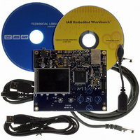
Evaluation Board, Software and Documentation
Processor To Be Evaluated
AT32UC3A0512
Processor Series
AVR
Data Bus Width
32 bit
Interface Type
USART, TWI, USB, SPI, Ethernet
Operating Supply Voltage
3.3 V
Silicon Manufacturer
Atmel
Core Architecture
AVR
Core Sub-architecture
AVR UC3
Silicon Core Number
AT32UC3A0512
Silicon Family Name
AVR
Kit Contents
Board CD Docs
Rohs Compliant
Yes
For Use With/related Products
AT32UC3A0
Lead Free Status / RoHS Status
Lead free / RoHS Compliant


26.7.4.2
32058J–AVR32–04/11
Parity
The USART supports five parity modes selected by programming the PAR field in the Mode
Register (MR). The PAR field also enables the Multidrop mode, see
321. Even and odd parity bit generation and error detection are supported.
If even parity is selected, the parity generator of the transmitter drives the parity bit at 0 if a num-
ber of 1s in the character data bit is even, and at 1 if the number of 1s is odd. Accordingly, the
receiver parity checker counts the number of received 1s and reports a parity error if the sam-
pled parity bit does not correspond. If odd parity is selected, the parity generator of the
transmitter drives the parity bit at 1 if a number of 1s in the character data bit is even, and at 0 if
the number of 1s is odd. Accordingly, the receiver parity checker counts the number of received
1s and reports a parity error if the sampled parity bit does not correspond. If the mark parity is
used, the parity generator of the transmitter drives the parity bit at 1 for all characters. The
receiver parity checker reports an error if the parity bit is sampled at 0. If the space parity is
used, the parity generator of the transmitter drives the parity bit at 0 for all characters. The
receiver parity checker reports an error if the parity bit is sampled at 1. If parity is disabled, the
transmitter does not generate any parity bit and the receiver does not report any parity error.
Table 26-6 on page 320
ASCII “A”) depending on the configuration of the USART. Because there are two bits at 1, 1 bit is
added when a parity is odd, or 0 is added when a parity is even.
Table 26-6.
When the receiver detects a parity error, it sets the PARE (Parity Error) bit in the Channel Status
Register (CSR). The PARE bit can be cleared by writing the Control Register (CR) with the RST-
STA bit at 1.
Character
A
A
A
A
A
Figure 26-22 on page 321
Parity Bit Examples
shows an example of the parity bit for the character 0x41 (character
Hexa
0x41
0x41
0x41
0x41
0x41
illustrates the parity bit status setting and clearing.
0100 0001
0100 0001
0100 0001
0100 0001
0100 0001
Binary
Parity Bit
None
1
0
1
0
”Multidrop Mode” on page
AT32UC3A
Parity Mode
Space
None
Even
Mark
Odd
320
Related parts for ATEVK1105
Image
Part Number
Description
Manufacturer
Datasheet
Request
R

Part Number:
Description:
DEV KIT FOR AVR/AVR32
Manufacturer:
Atmel
Datasheet:

Part Number:
Description:
INTERVAL AND WIPE/WASH WIPER CONTROL IC WITH DELAY
Manufacturer:
ATMEL Corporation
Datasheet:
Part Number:
Description:
Low-Voltage Voice-Switched IC for Hands-Free Operation
Manufacturer:
ATMEL Corporation
Datasheet:
Part Number:
Description:
MONOLITHIC INTEGRATED FEATUREPHONE CIRCUIT
Manufacturer:
ATMEL Corporation
Datasheet:
Part Number:
Description:
AM-FM Receiver IC U4255BM-M
Manufacturer:
ATMEL Corporation
Datasheet:
Part Number:
Description:
Monolithic Integrated Feature Phone Circuit
Manufacturer:
ATMEL Corporation
Datasheet:
Part Number:
Description:
Multistandard Video-IF and Quasi Parallel Sound Processing
Manufacturer:
ATMEL Corporation
Datasheet:
Part Number:
Description:
High-performance EE PLD
Manufacturer:
ATMEL Corporation
Datasheet:
Part Number:
Description:
8-bit Flash Microcontroller
Manufacturer:
ATMEL Corporation
Datasheet:
Part Number:
Description:
2-Wire Serial EEPROM
Manufacturer:
ATMEL Corporation
Datasheet: