ATEVK1105 Atmel, ATEVK1105 Datasheet - Page 762
ATEVK1105
Manufacturer Part Number
ATEVK1105
Description
KIT EVAL FOR AT32UC3A0
Manufacturer
Atmel
Series
AVR®32r
Type
MCUr
Datasheets
1.ATAVRONE-PROBECBL.pdf
(16 pages)
2.ATEVK1104.pdf
(826 pages)
3.ATEVK1105.pdf
(28 pages)
Specifications of ATEVK1105
Contents
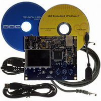
Evaluation Board, Software and Documentation
Processor To Be Evaluated
AT32UC3A0512
Processor Series
AVR
Data Bus Width
32 bit
Interface Type
USART, TWI, USB, SPI, Ethernet
Operating Supply Voltage
3.3 V
Silicon Manufacturer
Atmel
Core Architecture
AVR
Core Sub-architecture
AVR UC3
Silicon Core Number
AT32UC3A0512
Silicon Family Name
AVR
Kit Contents
Board CD Docs
Rohs Compliant
Yes
For Use With/related Products
AT32UC3A0
Lead Free Status / RoHS Status
Lead free / RoHS Compliant


37. Boot Sequence
37.1
37.2
32058J–AVR32–04/11
Starting of clocks
Fetching of initial instructions
This chapter summarizes the boot sequence of the AT32UC3A. The behaviour after power-up is
controlled by the Power Manager. For specific details, refer to
(PM)” on page
After power-up, the device will be held in a reset state by the Power-On Reset circuitry, until the
power has stabilized throughout the device. Once the power has stabilized, the device will use
the internal RC Oscillator as clock source.
On system start-up, the PLLs are disabled. All clocks to all modules are running. No clocks have
a divided frequency, all parts of the system recieves a clock with the same frequency as the
internal RC Oscillator.
After reset has been released, the AVR32 UC CPU starts fetching instructions from the reset
address, which is 0x8000_0000. This address points to the first address in the internal Flash.
The code read from the internal Flash is free to configure the system to use for example the
PLLs, to divide the frequency of the clock routed to some of the peripherals, and to gate the
clocks to unused peripherals.
53.
Section 13. ”Power Manager
AT32UC3A
762
Related parts for ATEVK1105
Image
Part Number
Description
Manufacturer
Datasheet
Request
R

Part Number:
Description:
DEV KIT FOR AVR/AVR32
Manufacturer:
Atmel
Datasheet:

Part Number:
Description:
INTERVAL AND WIPE/WASH WIPER CONTROL IC WITH DELAY
Manufacturer:
ATMEL Corporation
Datasheet:
Part Number:
Description:
Low-Voltage Voice-Switched IC for Hands-Free Operation
Manufacturer:
ATMEL Corporation
Datasheet:
Part Number:
Description:
MONOLITHIC INTEGRATED FEATUREPHONE CIRCUIT
Manufacturer:
ATMEL Corporation
Datasheet:
Part Number:
Description:
AM-FM Receiver IC U4255BM-M
Manufacturer:
ATMEL Corporation
Datasheet:
Part Number:
Description:
Monolithic Integrated Feature Phone Circuit
Manufacturer:
ATMEL Corporation
Datasheet:
Part Number:
Description:
Multistandard Video-IF and Quasi Parallel Sound Processing
Manufacturer:
ATMEL Corporation
Datasheet:
Part Number:
Description:
High-performance EE PLD
Manufacturer:
ATMEL Corporation
Datasheet:
Part Number:
Description:
8-bit Flash Microcontroller
Manufacturer:
ATMEL Corporation
Datasheet:
Part Number:
Description:
2-Wire Serial EEPROM
Manufacturer:
ATMEL Corporation
Datasheet: