ATEVK1105 Atmel, ATEVK1105 Datasheet - Page 55
ATEVK1105
Manufacturer Part Number
ATEVK1105
Description
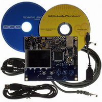
KIT EVAL FOR AT32UC3A0
Manufacturer
Atmel
Series
AVR®32r
Type
MCUr
Datasheets
1.ATAVRONE-PROBECBL.pdf
(16 pages)
2.ATEVK1104.pdf
(826 pages)
3.ATEVK1105.pdf
(28 pages)
Specifications of ATEVK1105
Contents
Evaluation Board, Software and Documentation
Processor To Be Evaluated
AT32UC3A0512
Processor Series
AVR
Data Bus Width
32 bit
Interface Type
USART, TWI, USB, SPI, Ethernet
Operating Supply Voltage
3.3 V
Silicon Manufacturer
Atmel
Core Architecture
AVR
Core Sub-architecture
AVR UC3
Silicon Core Number
AT32UC3A0512
Silicon Family Name
AVR
Kit Contents
Board CD Docs
Rohs Compliant
Yes
For Use With/related Products
AT32UC3A0
Lead Free Status / RoHS Status
Lead free / RoHS Compliant


13.4
13.4.1
13.4.2
13.4.3
13.5
13.5.1
13.5.2
32058J–AVR32–04/11
Product Dependencies
Functional Description
I/O Lines
Interrupt
Clock implementation
Slow clock
Oscillator 0 and 1 operation
The PM provides a number of generic clock outputs, which can be connected to output pins,
multiplexed with GPIO lines. The programmer must first program the GPIO controller to assign
these pins to their peripheral function. If the I/O pins of the PM are not used by the application,
they can be used for other purposes by the GPIO controller.
The PM interrupt line is connected to one of the internal sources of the interrupt controller. Using
the PM interrupt requires the interrupt controller to be programmed first.
In AT32UC3A, the HSB shares the source clock with the CPU. This means that writing to the
HSBDIV and HSBSEL bits in CKSEL has no effect. These bits will always read the same as
CPUDIV and CPUSEL.
The slow clock is generated from an internal RC oscillator which is always running, except in
Static mode. The slow clock can be used for the main clock in the device, as described in
chronous clocks” on page
measuring various delays in the Power Manager.
The RC oscillator has a 3 cycles startup time, and is always available when the CPU is running.
The RC oscillator operates at approximately 115 kHz, and can be calibrated to a narrow range
by the RCOSCCAL fuses. Software can also change RC oscillator calibration through the use of
the RCCR register. Please see the Electrical Characteristics section for details.
RC oscillator can also be used as the RTC clock when crystal accuracy is not required.
The two main oscillators are designed to be used with an external 450 kHz to 16 MHz crystal
and two biasing capacitors, as shown in
in the device, as described in
source for the generic clocks, as described in
The oscillators are disabled by default after reset. When the oscillators are disabled, the XIN and
XOUT pins can be used as general purpose I/Os. When the oscillators are configured to use an
external clock, the clock must be applied to the XIN pin while the XOUT pin can be used as a
general purpose I/O.
The oscillators can be enabled by writing to the OSCnEN bits in MCCTRL. Operation mode
(external clock or crystal) is chosen by writing to the MODE field in OSCCTRLn. Oscillators are
automatically switched off in certain sleep modes to reduce power consumption, as described in
Section 13.5.7 on page
After a hard reset, or when waking up from a sleep mode that disabled the oscillators, the oscil-
lators may need a certain amount of time to stabilize on the correct frequency. This start-up time
can be set in the OSCCTRLn register.
60.
58. The slow clock is also used for the Watchdog Timer and
”Synchronous clocks” on page
Figure
”Generic clocks” on page
13-2. Oscillator 0 can be used for the main clock
58. Both oscillators can be used as
61.
AT32UC3A
”Syn-
55
Related parts for ATEVK1105
Image
Part Number
Description
Manufacturer
Datasheet
Request
R

Part Number:
Description:
DEV KIT FOR AVR/AVR32
Manufacturer:
Atmel
Datasheet:

Part Number:
Description:
INTERVAL AND WIPE/WASH WIPER CONTROL IC WITH DELAY
Manufacturer:
ATMEL Corporation
Datasheet:
Part Number:
Description:
Low-Voltage Voice-Switched IC for Hands-Free Operation
Manufacturer:
ATMEL Corporation
Datasheet:
Part Number:
Description:
MONOLITHIC INTEGRATED FEATUREPHONE CIRCUIT
Manufacturer:
ATMEL Corporation
Datasheet:
Part Number:
Description:
AM-FM Receiver IC U4255BM-M
Manufacturer:
ATMEL Corporation
Datasheet:
Part Number:
Description:
Monolithic Integrated Feature Phone Circuit
Manufacturer:
ATMEL Corporation
Datasheet:
Part Number:
Description:
Multistandard Video-IF and Quasi Parallel Sound Processing
Manufacturer:
ATMEL Corporation
Datasheet:
Part Number:
Description:
High-performance EE PLD
Manufacturer:
ATMEL Corporation
Datasheet:
Part Number:
Description:
8-bit Flash Microcontroller
Manufacturer:
ATMEL Corporation
Datasheet:
Part Number:
Description:
2-Wire Serial EEPROM
Manufacturer:
ATMEL Corporation
Datasheet: