ATEVK1105 Atmel, ATEVK1105 Datasheet - Page 452
ATEVK1105
Manufacturer Part Number
ATEVK1105
Description
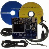
KIT EVAL FOR AT32UC3A0
Manufacturer
Atmel
Series
AVR®32r
Type
MCUr
Datasheets
1.ATAVRONE-PROBECBL.pdf
(16 pages)
2.ATEVK1104.pdf
(826 pages)
3.ATEVK1105.pdf
(28 pages)
Specifications of ATEVK1105
Contents
Evaluation Board, Software and Documentation
Processor To Be Evaluated
AT32UC3A0512
Processor Series
AVR
Data Bus Width
32 bit
Interface Type
USART, TWI, USB, SPI, Ethernet
Operating Supply Voltage
3.3 V
Silicon Manufacturer
Atmel
Core Architecture
AVR
Core Sub-architecture
AVR UC3
Silicon Core Number
AT32UC3A0512
Silicon Family Name
AVR
Kit Contents
Board CD Docs
Rohs Compliant
Yes
For Use With/related Products
AT32UC3A0
Lead Free Status / RoHS Status
Lead free / RoHS Compliant


29.6.1.3
29.6.1.4
29.6.1.5
29.6.1.6
32058J–AVR32–04/11
Transmit Buffer List
Address Matching
Interrupts
Transmitting Frames
Transmit data is read from the system memory These buffers are listed in another data structure
that also resides in main memory. This data structure (Transmit Buffer Queue) is a sequence of
descriptor entries (as defined in
To create this list of buffers:
The MACB register-pair hash address and the four specific address register-pairs must be writ-
ten with the required values. Each register-pair comprises a bottom register and top register,
with the bottom register being written first. The address matching is disabled for a particular reg-
ister-pair after the bottom-register has been written and re-enabled when the top register is
written.
may be written at any time, regardless of whether the receive circuits are enabled or disabled.
There are 14 interrupt conditions that are detected within the MACB. These are ORed to make a
single interrupt. This interrupt is passed to the interrupt controller. On receipt of the interrupt sig-
nal, the CPU enters the interrupt handler. To ascertain which interrupt has been generated, read
the interrupt status register. Note that this register clears itself when read. At reset, all interrupts
are disabled. To enable an interrupt, write to interrupt enable register with the pertinent interrupt
bit set to 1. To disable an interrupt, write to interrupt disable register with the pertinent interrupt
bit set to 1. To check whether an interrupt is enabled or disabled, read interrupt mask register: if
the bit is set to 1, the interrupt is disabled.
To set up a frame for transmission:
1. Allocate a number (n) of buffers of between 1 and 2047 bytes of data to be transmitted
2. Allocate an area 2n words for the transmit buffer descriptor entry in system memory
3. If fewer than 1024 buffers are defined, the last descriptor must be marked with the wrap
4. Write address of transmit buffer descriptor entry to MACB register transmit_buffer
5. The transmit circuits can then be enabled by writing to the network control register.
1. Enable transmit in the network control register.
2. Allocate an area of system memory for transmit data. This does not have to be contigu-
3. Set-up the transmit buffer list.
4. Set the network control register to enable transmission and enable interrupts.
5. Write data for transmission into these buffers.
6. Write the address to transmit buffer descriptor queue pointer.
7. Write control and length to word one of the transmit buffer descriptor entry.
8. Write to the transmit start bit in the network control register.
in system memory. Up to 128 buffers per frame are allowed.
and create N entries in this list. Mark all entries in this list as owned by MACB, i.e. bit 31
of word 1 set to 0.
bit — bit 30 in word 1 set to 1.
queue pointer.
ous, varying byte lengths can be used as long as they conclude on byte borders.
See Section “29.5.5” on page 446.
Table 29-2 on page
for details of address matching. Each register-pair
443) that points to this data structure.
AT32UC3A
452
Related parts for ATEVK1105
Image
Part Number
Description
Manufacturer
Datasheet
Request
R

Part Number:
Description:
DEV KIT FOR AVR/AVR32
Manufacturer:
Atmel
Datasheet:

Part Number:
Description:
INTERVAL AND WIPE/WASH WIPER CONTROL IC WITH DELAY
Manufacturer:
ATMEL Corporation
Datasheet:
Part Number:
Description:
Low-Voltage Voice-Switched IC for Hands-Free Operation
Manufacturer:
ATMEL Corporation
Datasheet:
Part Number:
Description:
MONOLITHIC INTEGRATED FEATUREPHONE CIRCUIT
Manufacturer:
ATMEL Corporation
Datasheet:
Part Number:
Description:
AM-FM Receiver IC U4255BM-M
Manufacturer:
ATMEL Corporation
Datasheet:
Part Number:
Description:
Monolithic Integrated Feature Phone Circuit
Manufacturer:
ATMEL Corporation
Datasheet:
Part Number:
Description:
Multistandard Video-IF and Quasi Parallel Sound Processing
Manufacturer:
ATMEL Corporation
Datasheet:
Part Number:
Description:
High-performance EE PLD
Manufacturer:
ATMEL Corporation
Datasheet:
Part Number:
Description:
8-bit Flash Microcontroller
Manufacturer:
ATMEL Corporation
Datasheet:
Part Number:
Description:
2-Wire Serial EEPROM
Manufacturer:
ATMEL Corporation
Datasheet: