ATEVK1105 Atmel, ATEVK1105 Datasheet - Page 254
ATEVK1105
Manufacturer Part Number
ATEVK1105
Description
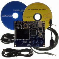
KIT EVAL FOR AT32UC3A0
Manufacturer
Atmel
Series
AVR®32r
Type
MCUr
Datasheets
1.ATAVRONE-PROBECBL.pdf
(16 pages)
2.ATEVK1104.pdf
(826 pages)
3.ATEVK1105.pdf
(28 pages)
Specifications of ATEVK1105
Contents
Evaluation Board, Software and Documentation
Processor To Be Evaluated
AT32UC3A0512
Processor Series
AVR
Data Bus Width
32 bit
Interface Type
USART, TWI, USB, SPI, Ethernet
Operating Supply Voltage
3.3 V
Silicon Manufacturer
Atmel
Core Architecture
AVR
Core Sub-architecture
AVR UC3
Silicon Core Number
AT32UC3A0512
Silicon Family Name
AVR
Kit Contents
Board CD Docs
Rohs Compliant
Yes
For Use With/related Products
AT32UC3A0
Lead Free Status / RoHS Status
Lead free / RoHS Compliant


AT32UC3A
NACK used in Slave Read mode:
0 = Each data byte has been correctly received by the Master.
1 = In read mode, a data byte has not been acknowledged by the Master. When NACK is set the programmer must not fill
THR even if TXRDY is set, because it means that the Master will stop the data transfer or re initiate it.
Note that in Slave Write mode all data are acknowledged by the TWI.
• ARBLST: Arbitration Lost (clear on read)
This bit is only used in Master mode.
0 = Arbitration won.
1 = Arbitration lost. Another master of the TWI bus has won the multi-master arbitration. TXCOMP is set at the same time.
• SCLWS: Clock Wait State (automatically set / reset)
This bit is only used in Slave mode.
0 = The clock is not stretched.
1 = The clock is stretched. THR / RHR buffer is not filled / emptied before the emission / reception of a new character.
SCLWS behavior can be seen in
Figure 24-26 on page 242
and
Figure 24-27 on page
243.
• EOSACC: End Of Slave Access (clear on read)
This bit is only used in Slave mode.
0 = A slave access is being performing.
1 = The Slave Access is finished. End Of Slave Access is automatically set as soon as SVACC is reset.
EOSACC behavior can be seen in
Figure 24-28 on page 244
and
Figure 24-29 on page 244
• ENDRX: End of RX buffer
This bit is only used in Master mode.
0 = The Receive Counter Register has not reached 0 since the last write in RCR or RNCR.
1 = The Receive Counter Register has reached 0 since the last write in RCR or RNCR.
• ENDTX: End of TX buffer
This bit is only used in Master mode.
0 = The Transmit Counter Register has not reached 0 since the last write in TCR or TNCR.
1 = The Transmit Counter Register has reached 0 since the last write in TCR or TNCR.
• RXBUFF: RX Buffer Full
This bit is only used in Master mode.
0 = RCR or RNCR have a value other than 0.
1 = Both RCR and RNCR have a value of 0.
• TXBUFE: TX Buffer Empty
This bit is only used in Master mode.
0 = TCR or TNCR have a value other than 0.
254
32058J-AVR32-04/11
Related parts for ATEVK1105
Image
Part Number
Description
Manufacturer
Datasheet
Request
R

Part Number:
Description:
DEV KIT FOR AVR/AVR32
Manufacturer:
Atmel
Datasheet:

Part Number:
Description:
INTERVAL AND WIPE/WASH WIPER CONTROL IC WITH DELAY
Manufacturer:
ATMEL Corporation
Datasheet:
Part Number:
Description:
Low-Voltage Voice-Switched IC for Hands-Free Operation
Manufacturer:
ATMEL Corporation
Datasheet:
Part Number:
Description:
MONOLITHIC INTEGRATED FEATUREPHONE CIRCUIT
Manufacturer:
ATMEL Corporation
Datasheet:
Part Number:
Description:
AM-FM Receiver IC U4255BM-M
Manufacturer:
ATMEL Corporation
Datasheet:
Part Number:
Description:
Monolithic Integrated Feature Phone Circuit
Manufacturer:
ATMEL Corporation
Datasheet:
Part Number:
Description:
Multistandard Video-IF and Quasi Parallel Sound Processing
Manufacturer:
ATMEL Corporation
Datasheet:
Part Number:
Description:
High-performance EE PLD
Manufacturer:
ATMEL Corporation
Datasheet:
Part Number:
Description:
8-bit Flash Microcontroller
Manufacturer:
ATMEL Corporation
Datasheet:
Part Number:
Description:
2-Wire Serial EEPROM
Manufacturer:
ATMEL Corporation
Datasheet: