ATEVK1105 Atmel, ATEVK1105 Datasheet - Page 44
ATEVK1105
Manufacturer Part Number
ATEVK1105
Description
KIT EVAL FOR AT32UC3A0
Manufacturer
Atmel
Series
AVR®32r
Type
MCUr
Datasheets
1.ATAVRONE-PROBECBL.pdf
(16 pages)
2.ATEVK1104.pdf
(826 pages)
3.ATEVK1105.pdf
(28 pages)
Specifications of ATEVK1105
Contents
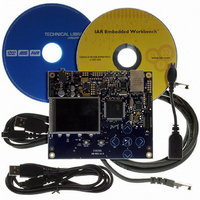
Evaluation Board, Software and Documentation
Processor To Be Evaluated
AT32UC3A0512
Processor Series
AVR
Data Bus Width
32 bit
Interface Type
USART, TWI, USB, SPI, Ethernet
Operating Supply Voltage
3.3 V
Silicon Manufacturer
Atmel
Core Architecture
AVR
Core Sub-architecture
AVR UC3
Silicon Core Number
AT32UC3A0512
Silicon Family Name
AVR
Kit Contents
Board CD Docs
Rohs Compliant
Yes
For Use With/related Products
AT32UC3A0
Lead Free Status / RoHS Status
Lead free / RoHS Compliant


12.4.3
12.5
12.6
32058J–AVR32–04/11
Nexus OCD AUX port connections
PDC handshake signals
SPIs
Each SPI can be connected to an internally divided clock:
Table 12-6.
If the OCD trace system is enabled, the trace system will take control over a number of pins, irre-
spectively of the PIO configuration. Two different OCD trace pin mappings are possible,
depending on the configuration of the OCD AXS register. For details, see the AVR32 UC Tech-
nical Reference Manual.
Table 12-7.
The PDC and the peripheral modules communicate through a set of handshake signals. The fol-
lowing table defines the valid settings for the Peripheral Identifier (PID) in the PDC Peripheral
Select Register (PSR).
Table 12-8.
SPI
0
1
Pin
EVTI_N
MDO[5]
MDO[4]
MDO[3]
MDO[2]
MDO[1]
MDO[0]
EVTO_N
MCKO
MSEO[1]
MSEO[0]
PID Value
0
1
2
3
SPI clock connections
Nexus OCD AUX port connections
PDC Handshake Signals
AXS=0
PB19
PB16
PB14
PB13
PB12
PB11
PB10
PB20
PB21
PB04
PB17
Peripheral module & direction
ADC
SSC - RX
USART0 - RX
USART1 - RX
Source
Internal
Name
CLK_DIV
AXS=1
PA08
PA27
PA26
PA25
PA24
PA23
PA22
PB20
PA21
PA07
PA28
Connection
PBA clock or
PBA clock / 32
AT32UC3A
44
Related parts for ATEVK1105
Image
Part Number
Description
Manufacturer
Datasheet
Request
R

Part Number:
Description:
DEV KIT FOR AVR/AVR32
Manufacturer:
Atmel
Datasheet:

Part Number:
Description:
INTERVAL AND WIPE/WASH WIPER CONTROL IC WITH DELAY
Manufacturer:
ATMEL Corporation
Datasheet:
Part Number:
Description:
Low-Voltage Voice-Switched IC for Hands-Free Operation
Manufacturer:
ATMEL Corporation
Datasheet:
Part Number:
Description:
MONOLITHIC INTEGRATED FEATUREPHONE CIRCUIT
Manufacturer:
ATMEL Corporation
Datasheet:
Part Number:
Description:
AM-FM Receiver IC U4255BM-M
Manufacturer:
ATMEL Corporation
Datasheet:
Part Number:
Description:
Monolithic Integrated Feature Phone Circuit
Manufacturer:
ATMEL Corporation
Datasheet:
Part Number:
Description:
Multistandard Video-IF and Quasi Parallel Sound Processing
Manufacturer:
ATMEL Corporation
Datasheet:
Part Number:
Description:
High-performance EE PLD
Manufacturer:
ATMEL Corporation
Datasheet:
Part Number:
Description:
8-bit Flash Microcontroller
Manufacturer:
ATMEL Corporation
Datasheet:
Part Number:
Description:
2-Wire Serial EEPROM
Manufacturer:
ATMEL Corporation
Datasheet: