ATEVK1105 Atmel, ATEVK1105 Datasheet - Page 325
ATEVK1105
Manufacturer Part Number
ATEVK1105
Description
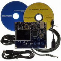
KIT EVAL FOR AT32UC3A0
Manufacturer
Atmel
Series
AVR®32r
Type
MCUr
Datasheets
1.ATAVRONE-PROBECBL.pdf
(16 pages)
2.ATEVK1104.pdf
(826 pages)
3.ATEVK1105.pdf
(28 pages)
Specifications of ATEVK1105
Contents
Evaluation Board, Software and Documentation
Processor To Be Evaluated
AT32UC3A0512
Processor Series
AVR
Data Bus Width
32 bit
Interface Type
USART, TWI, USB, SPI, Ethernet
Operating Supply Voltage
3.3 V
Silicon Manufacturer
Atmel
Core Architecture
AVR
Core Sub-architecture
AVR UC3
Silicon Core Number
AT32UC3A0512
Silicon Family Name
AVR
Kit Contents
Board CD Docs
Rohs Compliant
Yes
For Use With/related Products
AT32UC3A0
Lead Free Status / RoHS Status
Lead free / RoHS Compliant


Figure 26-26. Break Transmission
26.7.4.8
26.7.4.9
32058J–AVR32–04/11
Baud Rate
TXEMPTY
US_CR
TXRDY
Clock
Write
TXD
Receive Break
Hardware Handshaking
Start
Bit
D0
D1
D2
STTBRK = 1
After the break condition, the transmitter returns the TXD line to 1 for a minimum of 12 bit times.
Thus, the transmitter ensures that the remote receiver detects correctly the end of break and the
start of the next character. If the timeguard is programmed with a value higher than 12, the TXD
line is held high for the timeguard period.
After holding the TXD line for this period, the transmitter resumes normal operations.
Figure 26-26 on page 325
(STPBRK) commands on the TXD line.
The receiver detects a break condition when all data, parity and stop bits are low. This corre-
sponds to detecting a framing error with data at 0x00, but FRAME remains low.
When the low stop bit is detected, the receiver asserts the RXBRK bit in CSR. This bit may be
cleared by writing the Control Register (CR) with the bit RSTSTA at 1.
An end of receive break is detected by a high level for at least 2/16 of a bit period in asynchro-
nous operating mode or one sample at high level in synchronous operating mode. The end of
break detection also asserts the RXBRK bit.
The USART features a hardware handshaking out-of-band flow control. The RTS and CTS pins
are used to connect with the remote device, as shown in
Figure 26-27. Connection with a Remote Device for Hardware Handshaking
D3
D4
D5
D6
D7
Parity
Bit
Stop
Bit
USART
illustrates the effect of both the Start Break (STTBRK) and Stop Break
TXD
RXD
CTS
RTS
Break Transmission
STPBRK = 1
Figure 26-27 on page
RXD
TXD
RTS
CTS
Remote
Device
End of Break
AT32UC3A
325.
325
Related parts for ATEVK1105
Image
Part Number
Description
Manufacturer
Datasheet
Request
R

Part Number:
Description:
DEV KIT FOR AVR/AVR32
Manufacturer:
Atmel
Datasheet:

Part Number:
Description:
INTERVAL AND WIPE/WASH WIPER CONTROL IC WITH DELAY
Manufacturer:
ATMEL Corporation
Datasheet:
Part Number:
Description:
Low-Voltage Voice-Switched IC for Hands-Free Operation
Manufacturer:
ATMEL Corporation
Datasheet:
Part Number:
Description:
MONOLITHIC INTEGRATED FEATUREPHONE CIRCUIT
Manufacturer:
ATMEL Corporation
Datasheet:
Part Number:
Description:
AM-FM Receiver IC U4255BM-M
Manufacturer:
ATMEL Corporation
Datasheet:
Part Number:
Description:
Monolithic Integrated Feature Phone Circuit
Manufacturer:
ATMEL Corporation
Datasheet:
Part Number:
Description:
Multistandard Video-IF and Quasi Parallel Sound Processing
Manufacturer:
ATMEL Corporation
Datasheet:
Part Number:
Description:
High-performance EE PLD
Manufacturer:
ATMEL Corporation
Datasheet:
Part Number:
Description:
8-bit Flash Microcontroller
Manufacturer:
ATMEL Corporation
Datasheet:
Part Number:
Description:
2-Wire Serial EEPROM
Manufacturer:
ATMEL Corporation
Datasheet: