ATEVK1105 Atmel, ATEVK1105 Datasheet - Page 305
ATEVK1105
Manufacturer Part Number
ATEVK1105
Description
KIT EVAL FOR AT32UC3A0
Manufacturer
Atmel
Series
AVR®32r
Type
MCUr
Datasheets
1.ATAVRONE-PROBECBL.pdf
(16 pages)
2.ATEVK1104.pdf
(826 pages)
3.ATEVK1105.pdf
(28 pages)
Specifications of ATEVK1105
Contents
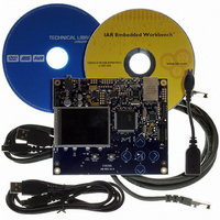
Evaluation Board, Software and Documentation
Processor To Be Evaluated
AT32UC3A0512
Processor Series
AVR
Data Bus Width
32 bit
Interface Type
USART, TWI, USB, SPI, Ethernet
Operating Supply Voltage
3.3 V
Silicon Manufacturer
Atmel
Core Architecture
AVR
Core Sub-architecture
AVR UC3
Silicon Core Number
AT32UC3A0512
Silicon Family Name
AVR
Kit Contents
Board CD Docs
Rohs Compliant
Yes
For Use With/related Products
AT32UC3A0
Lead Free Status / RoHS Status
Lead free / RoHS Compliant


26.7.1
Figure 26-3. Baud Rate Generator
26.7.1.1
32058J–AVR32–04/11
Baud Rate Generator
CLK_USART/DIV
CLK
CLK_USART
Baud Rate in Asynchronous Mode
Reserved
USCLKS
The Baud Rate Generator provides the bit period clock named the Baud Rate Clock to both the
receiver and the transmitter.
The Baud Rate Generator clock source can be selected by setting the USCLKS field in the Mode
Register (MR) between:
The Baud Rate Generator is based upon a 16-bit divider, which is programmed with the CD field
of the Baud Rate Generator Register (BRGR). If CD is programmed at 0, the Baud Rate Gener-
ator does not generate any clock. If CD is programmed at 1, the divider is bypassed and
becomes inactive.
If the external CLK clock is selected, the duration of the low and high levels of the signal pro-
vided on the CLK pin must be longer than a CLK_USART period. The frequency of the signal
provided on CLK must be at least 4.5 times lower than CLK_USART.
If the USART is programmed to operate in asynchronous mode, the selected clock is first
divided by CD, which is field programmed in the Baud Rate Generator Register (BRGR). The
resulting clock is provided to the receiver as a sampling clock and then divided by 16 or 8,
depending on the programming of the OVER bit in MR.
If OVER is set to 1, the receiver sampling is 8 times higher than the baud rate clock. If OVER is
cleared, the sampling is performed at 16 times the baud rate clock.
The following formula performs the calculation of the Baud Rate.
0
1
2
3
•the CLK_USART
•a division of the CLK_USART, the divider being product dependent, but generally set to 8
•the external clock, available on the CLK pin
Baudrate
16-bit Counter
=
CD
--------------------------------------------
(
8 2 Over
SelectedClock
(
–
USCLKS= 3
)CD
0
SYNC
)
CD
>1
0
1
0
1
OVER
Sampling
Divider
FIDI
0
1
SYNC
CLK
AT32UC3A
BaudRate
Sampling
Clock
Clock
305
Related parts for ATEVK1105
Image
Part Number
Description
Manufacturer
Datasheet
Request
R

Part Number:
Description:
DEV KIT FOR AVR/AVR32
Manufacturer:
Atmel
Datasheet:

Part Number:
Description:
INTERVAL AND WIPE/WASH WIPER CONTROL IC WITH DELAY
Manufacturer:
ATMEL Corporation
Datasheet:
Part Number:
Description:
Low-Voltage Voice-Switched IC for Hands-Free Operation
Manufacturer:
ATMEL Corporation
Datasheet:
Part Number:
Description:
MONOLITHIC INTEGRATED FEATUREPHONE CIRCUIT
Manufacturer:
ATMEL Corporation
Datasheet:
Part Number:
Description:
AM-FM Receiver IC U4255BM-M
Manufacturer:
ATMEL Corporation
Datasheet:
Part Number:
Description:
Monolithic Integrated Feature Phone Circuit
Manufacturer:
ATMEL Corporation
Datasheet:
Part Number:
Description:
Multistandard Video-IF and Quasi Parallel Sound Processing
Manufacturer:
ATMEL Corporation
Datasheet:
Part Number:
Description:
High-performance EE PLD
Manufacturer:
ATMEL Corporation
Datasheet:
Part Number:
Description:
8-bit Flash Microcontroller
Manufacturer:
ATMEL Corporation
Datasheet:
Part Number:
Description:
2-Wire Serial EEPROM
Manufacturer:
ATMEL Corporation
Datasheet: