ATEVK1105 Atmel, ATEVK1105 Datasheet - Page 88
ATEVK1105
Manufacturer Part Number
ATEVK1105
Description
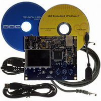
KIT EVAL FOR AT32UC3A0
Manufacturer
Atmel
Series
AVR®32r
Type
MCUr
Datasheets
1.ATAVRONE-PROBECBL.pdf
(16 pages)
2.ATEVK1104.pdf
(826 pages)
3.ATEVK1105.pdf
(28 pages)
Specifications of ATEVK1105
Contents
Evaluation Board, Software and Documentation
Processor To Be Evaluated
AT32UC3A0512
Processor Series
AVR
Data Bus Width
32 bit
Interface Type
USART, TWI, USB, SPI, Ethernet
Operating Supply Voltage
3.3 V
Silicon Manufacturer
Atmel
Core Architecture
AVR
Core Sub-architecture
AVR UC3
Silicon Core Number
AT32UC3A0512
Silicon Family Name
AVR
Kit Contents
Board CD Docs
Rohs Compliant
Yes
For Use With/related Products
AT32UC3A0
Lead Free Status / RoHS Status
Lead free / RoHS Compliant


14.5.1.2
14.5.1.3
14.5.1.4
14.5.1.5
32058J–AVR32–04/11
Counter operation
RTC Interrupt
RTC wakeup
Busy bit
The CLK32 bit selects either the RC oscillator or the 32 KHz oscillator as clock source for the
prescaler.
The PSEL bitfield selects the prescaler tapping, selecting the source clock for the RTC:
When enabled, the RTC will increment until it reaches TOP, and then wrap to 0x0. The status bit
TOPI in ISR is set when this occurs. From 0x0 the counter will count TOP+1 cycles of the source
clock before it wraps back to 0x0.
The RTC count value can be read from or written to the register VAL. Due to synchronization,
continuous reading of the VAL with the lowest prescaler setting will skip every other value.
Writing the TOPI bit in IER enables the RTC interrupt, while writing the corresponding bit in IDR
disables the RTC interrupt. IMR can be read to see whether or not the interrupt is enabled. If
enabled, an interrupt will be generated if the TOPI flag in ISR is set. The flag can be cleared by
writing TOPI in ICR to one.
The RTC interrupt can wake the CPU from all sleep modes except DeepStop and Static mode.
The RTC can also wake up the CPU directly without triggering an interrupt when the TOPI flag in
ISR is set. In this case, the CPU will continue executing from the instruction following the sleep
instruction.
This direct RTC wakeup is enabled by writing the WAKE_EN bit in the CTRL register to one.
When the CPU wakes from sleep, the WAKE_EN bit must be written to zero to clear the internal
wake signal to the sleep controller, otherwise a new sleep instruction will have no effect.
The RTC wakeup is available in all sleep modes except Static mode. The RTC wakeup can be
configured independently of the RTC interrupt.
Due to the crossing of clock domains, the RTC uses a few clock cycles to propagate the values
stored in CTRL, TOP, and VAL to the RTC. The BUSY bit in CTRL indicates that a register write
is still going on and all writes to TOP, CTRL, and VAL will be discarded until BUSY goes low
again.
f
RTC
= 2
-(PSEL+1)
* (f
RC
or 32 KHz)
AT32UC3A
88
Related parts for ATEVK1105
Image
Part Number
Description
Manufacturer
Datasheet
Request
R

Part Number:
Description:
DEV KIT FOR AVR/AVR32
Manufacturer:
Atmel
Datasheet:

Part Number:
Description:
INTERVAL AND WIPE/WASH WIPER CONTROL IC WITH DELAY
Manufacturer:
ATMEL Corporation
Datasheet:
Part Number:
Description:
Low-Voltage Voice-Switched IC for Hands-Free Operation
Manufacturer:
ATMEL Corporation
Datasheet:
Part Number:
Description:
MONOLITHIC INTEGRATED FEATUREPHONE CIRCUIT
Manufacturer:
ATMEL Corporation
Datasheet:
Part Number:
Description:
AM-FM Receiver IC U4255BM-M
Manufacturer:
ATMEL Corporation
Datasheet:
Part Number:
Description:
Monolithic Integrated Feature Phone Circuit
Manufacturer:
ATMEL Corporation
Datasheet:
Part Number:
Description:
Multistandard Video-IF and Quasi Parallel Sound Processing
Manufacturer:
ATMEL Corporation
Datasheet:
Part Number:
Description:
High-performance EE PLD
Manufacturer:
ATMEL Corporation
Datasheet:
Part Number:
Description:
8-bit Flash Microcontroller
Manufacturer:
ATMEL Corporation
Datasheet:
Part Number:
Description:
2-Wire Serial EEPROM
Manufacturer:
ATMEL Corporation
Datasheet: