EVB9S12XEP100 Freescale Semiconductor, EVB9S12XEP100 Datasheet - Page 315
EVB9S12XEP100
Manufacturer Part Number
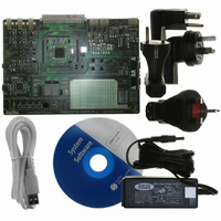
EVB9S12XEP100
Description
BOARD EVAL FOR MC9S12XEP100
Manufacturer
Freescale Semiconductor
Type
MCUr
Datasheet
1.EVB9S12XEP100.pdf
(1328 pages)
Specifications of EVB9S12XEP100
Contents
Module and Misc Hardware
Processor To Be Evaluated
MC9S12XEP100
Data Bus Width
16 bit
Interface Type
RS-232
Silicon Manufacturer
Freescale
Core Architecture
S12
Core Sub-architecture
S12
Silicon Core Number
MC9S12
Silicon Family Name
S12XE
Rohs Compliant
Yes
For Use With/related Products
MC9S12XEP100
Lead Free Status / RoHS Status
Lead free / RoHS Compliant


8.3.2.3
Read: Anytime
Write: Bits 7:6 only when S12XDBG is neither secure nor armed.
Freescale Semiconductor
Address: 0x0022
TSOURCE
Because of an order from the United States International Trade Commission, BGA-packaged product lines and partnumbers
TRCMOD
TRANGE
TALIGN
Reset
indicated here currently are not available from Freescale for import or sale in the United States prior to September 2010
Field
7–6
5–4
3–2
1–0
W
R
Bits 5:0 anytime the module is disarmed.
Trace Source Control Bits — The TSOURCE bits select the data source for the tracing session. If the MCU
system is secured, these bits cannot be set and tracing is inhibited. See
Trace Range Bits — The TRANGE bits allow filtering of trace information from a selected address range when
tracing from the CPU12X in Detail Mode. The XGATE tracing range cannot be narrowed using these bits. To use
a comparator for range filtering, the corresponding COMPE and SRC bits must remain cleared. If the COMPE
bit is not clear then the comparator will also be used to generate state sequence triggers. If the corresponding
SRC bit is set the comparator is mapped to the XGATE buses, the TRANGE bits have no effect on the valid
address range, memory accesses within the whole memory map are traced. See
Trace Mode Bits — See
information is stored. In Loop1 Mode, change of flow information is stored but redundant entries into trace
memory are inhibited. In Detail Mode, address and data for all memory and register accesses is stored. See
Table
Trigger Align Bits — These bits control whether the trigger is aligned to the beginning, end or the middle of a
tracing session. See
Debug Trace Control Register (DBGTCR)
0
7
1. No range limitations are allowed. Thus tracing operates as if TRANGE = 00.
2. No Detail Mode tracing supported. If TRCMOD = 10, no information is stored.
TSOURCE
8-13.
TSOURCE
11
10
00
01
1,(2)
(1)
0
6
Figure 8-5. Debug Trace Control Register (DBGTCR)
Table 8-11. TSOURCE — Trace Source Bit Encoding
Table
MC9S12XE-Family Reference Manual Rev. 1.23
Table 8-10. DBGTCR Field Descriptions
Section 8.4.5.2
8-14.
5
0
TRANGE
for detailed Trace Mode descriptions. In Normal Mode, change of flow
Both CPU12X and XGATE
0
4
No tracing requested
Tracing Source
Description
CPU12X
XGATE
0
3
TRCMOD
Chapter 8 S12X Debug (S12XDBGV3) Module
Table
2
0
8-11.
Table
8-12.
0
1
TALIGN
0
0
315
Related parts for EVB9S12XEP100
Image
Part Number
Description
Manufacturer
Datasheet
Request
R

Part Number:
Description:
Manufacturer:
Freescale Semiconductor, Inc
Datasheet:
Part Number:
Description:
Manufacturer:
Freescale Semiconductor, Inc
Datasheet:
Part Number:
Description:
Manufacturer:
Freescale Semiconductor, Inc
Datasheet:
Part Number:
Description:
Manufacturer:
Freescale Semiconductor, Inc
Datasheet:
Part Number:
Description:
Manufacturer:
Freescale Semiconductor, Inc
Datasheet:
Part Number:
Description:
Manufacturer:
Freescale Semiconductor, Inc
Datasheet:
Part Number:
Description:
Manufacturer:
Freescale Semiconductor, Inc
Datasheet:
Part Number:
Description:
Manufacturer:
Freescale Semiconductor, Inc
Datasheet:
Part Number:
Description:
Manufacturer:
Freescale Semiconductor, Inc
Datasheet:
Part Number:
Description:
Manufacturer:
Freescale Semiconductor, Inc
Datasheet:
Part Number:
Description:
Manufacturer:
Freescale Semiconductor, Inc
Datasheet:
Part Number:
Description:
Manufacturer:
Freescale Semiconductor, Inc
Datasheet:
Part Number:
Description:
Manufacturer:
Freescale Semiconductor, Inc
Datasheet:
Part Number:
Description:
Manufacturer:
Freescale Semiconductor, Inc
Datasheet:
Part Number:
Description:
Manufacturer:
Freescale Semiconductor, Inc
Datasheet: