EVB9S12XEP100 Freescale Semiconductor, EVB9S12XEP100 Datasheet - Page 577
EVB9S12XEP100
Manufacturer Part Number
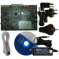
EVB9S12XEP100
Description
BOARD EVAL FOR MC9S12XEP100
Manufacturer
Freescale Semiconductor
Type
MCUr
Datasheet
1.EVB9S12XEP100.pdf
(1328 pages)
Specifications of EVB9S12XEP100
Contents
Module and Misc Hardware
Processor To Be Evaluated
MC9S12XEP100
Data Bus Width
16 bit
Interface Type
RS-232
Silicon Manufacturer
Freescale
Core Architecture
S12
Core Sub-architecture
S12
Silicon Core Number
MC9S12
Silicon Family Name
S12XE
Rohs Compliant
Yes
For Use With/related Products
MC9S12XEP100
Lead Free Status / RoHS Status
Lead free / RoHS Compliant


14.4.1.2
An internal compare channel whose output drives OCx may be programmed before the timer drives the
output compare state (OCx). The required output of the compare logic can be disconnected from the pin,
leaving it driven by the GP IO port, by setting the appropriate OCPDx bit before enabling the output
compare channel (by default the OCPD bits are cleared which would enable the output compare logic to
drive the pin as soon as the timer output compare channel is enabled). The desired initial state can then be
configured in the internal output compare logic by forcing a compare action with the logic disconnected
from the IO (by writing a one to CFORCx bit with TIOSx, OCPDx and TEN bits set to one). Clearing the
output compare disconnect bit (OCPDx) will then allow the internal compare logic to drive the
programmed state to OCx. This allows a glitch free switching between general purpose I/O and timer
output functionality.
14.4.1.3
There are four 8-bit pulse accumulators with four 8-bit holding registers associated with the four IC
buffered channels 3–0. A pulse accumulator counts the number of active edges at the input of its channel.
The minimum pulse width for the PAI input is greater than two bus clocks.The maximum input frequency
on the pulse accumulator channel is one half the bus frequency or Eclk.
The user can prevent the 8-bit pulse accumulators from counting further than 0x00FF by utilizing the
PACMX control bit in the ICSYS register. In this case, a value of 0x00FF means that 255 counts or more
have occurred.
Each pair of pulse accumulators can be used as a 16-bit pulse accumulator (see
Pulse accumulator B operates only as an event counter, it does not feature gated time accumulation mode.
The edge control for pulse accumulator B as a 16-bit pulse accumulator is defined by TCTL4[1:0].
To operate the 16-bit pulse accumulators A and B (PACA and PACB) independently of input capture or
output compare 7 and 0 respectively, the user must set the corresponding bits: IOSx = 1, OMx = 0, and
OLx = 0. OC7M7 or OC7M0 in the OC7M register must also be cleared.
There are two modes of operation for the pulse accumulators:
Freescale Semiconductor
Because of an order from the United States International Trade Commission, BGA-packaged product lines and partnumbers
indicated here currently are not available from Freescale for import or sale in the United States prior to September 2010
3. Input pulses with a duration between (DLY_CNT – 1) and DLY_CNT cycles may be rejected or
4. Input pulses with a duration of DLY_CNT or longer are accepted.
•
•
accepted, depending on their relative alignment with the sample points.
Pulse accumulator latch mode
The value of the pulse accumulator is transferred to its holding register when the modulus down-
counter reaches zero, a write 0x0000 to the modulus counter or when the force latch control bit
ICLAT is written.
At the same time the pulse accumulator is cleared.
Pulse accumulator queue mode
When queue mode is enabled, reads of an input capture holding register will transfer the contents
of the associated pulse accumulator to its holding register.
OC Channel Initialization
Pulse Accumulators
MC9S12XE-Family Reference Manual Rev. 1.23
Chapter 14 Enhanced Capture Timer (ECT16B8CV3)
Figure
14-72).
577
Related parts for EVB9S12XEP100
Image
Part Number
Description
Manufacturer
Datasheet
Request
R

Part Number:
Description:
Manufacturer:
Freescale Semiconductor, Inc
Datasheet:
Part Number:
Description:
Manufacturer:
Freescale Semiconductor, Inc
Datasheet:
Part Number:
Description:
Manufacturer:
Freescale Semiconductor, Inc
Datasheet:
Part Number:
Description:
Manufacturer:
Freescale Semiconductor, Inc
Datasheet:
Part Number:
Description:
Manufacturer:
Freescale Semiconductor, Inc
Datasheet:
Part Number:
Description:
Manufacturer:
Freescale Semiconductor, Inc
Datasheet:
Part Number:
Description:
Manufacturer:
Freescale Semiconductor, Inc
Datasheet:
Part Number:
Description:
Manufacturer:
Freescale Semiconductor, Inc
Datasheet:
Part Number:
Description:
Manufacturer:
Freescale Semiconductor, Inc
Datasheet:
Part Number:
Description:
Manufacturer:
Freescale Semiconductor, Inc
Datasheet:
Part Number:
Description:
Manufacturer:
Freescale Semiconductor, Inc
Datasheet:
Part Number:
Description:
Manufacturer:
Freescale Semiconductor, Inc
Datasheet:
Part Number:
Description:
Manufacturer:
Freescale Semiconductor, Inc
Datasheet:
Part Number:
Description:
Manufacturer:
Freescale Semiconductor, Inc
Datasheet:
Part Number:
Description:
Manufacturer:
Freescale Semiconductor, Inc
Datasheet: