EVB9S12XEP100 Freescale Semiconductor, EVB9S12XEP100 Datasheet - Page 715
EVB9S12XEP100
Manufacturer Part Number
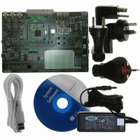
EVB9S12XEP100
Description
BOARD EVAL FOR MC9S12XEP100
Manufacturer
Freescale Semiconductor
Type
MCUr
Datasheet
1.EVB9S12XEP100.pdf
(1328 pages)
Specifications of EVB9S12XEP100
Contents
Module and Misc Hardware
Processor To Be Evaluated
MC9S12XEP100
Data Bus Width
16 bit
Interface Type
RS-232
Silicon Manufacturer
Freescale
Core Architecture
S12
Core Sub-architecture
S12
Silicon Core Number
MC9S12
Silicon Family Name
S12XE
Rohs Compliant
Yes
For Use With/related Products
MC9S12XEP100
Lead Free Status / RoHS Status
Lead free / RoHS Compliant


and the counter value and causes the state of the output to change during the period. The starting polarity
of the output is also selectable on a per channel basis. Shown below in
for the PWM timer.
19.4.2.1
Each PWM channel has an enable bit (PWMEx) to start its waveform output. When any of the PWMEx
bits are set (PWMEx = 1), the associated PWM output signal is enabled immediately. However, the actual
PWM waveform is not available on the associated PWM output until its clock source begins its next cycle
due to the synchronization of PWMEx and the clock source. An exception to this is when channels are
concatenated. Refer to
On the front end of the PWM timer, the clock is enabled to the PWM circuit by the PWMEx bit being high.
There is an edge-synchronizing circuit to guarantee that the clock will only be enabled or disabled at an
edge. When the channel is disabled (PWMEx = 0), the counter for the channel does not count.
Freescale Semiconductor
Because of an order from the United States International Trade Commission, BGA-packaged product lines and partnumbers
Clock Source
indicated here currently are not available from Freescale for import or sale in the United States prior to September 2010
PWMEx
(Clock Edge
PWM Enable
Sync)
Gate
The first PWM cycle after enabling the channel can be irregular.
Up/Down
Section 19.4.2.7, “PWM 16-Bit Functions”
8-Bit Counter
Figure 19-19. PWM Timer Channel Block Diagram
PWMCNTx
Q
Q
MC9S12XE-Family Reference Manual Rev. 1.23
Reset
T
R
NOTE
8-bit Compare =
8-bit Compare =
PWMDTYx
PWMPERx
CAEx
Chapter 19 Pulse-Width Modulator (S12PWM8B8CV1)
for more detail.
Figure 19-19
T
R
Q
Q
PPOLx
From Port PWMP
M
U
Data Register
X
is the block diagram
M
U
X
To Pin
Driver
715
Related parts for EVB9S12XEP100
Image
Part Number
Description
Manufacturer
Datasheet
Request
R

Part Number:
Description:
Manufacturer:
Freescale Semiconductor, Inc
Datasheet:
Part Number:
Description:
Manufacturer:
Freescale Semiconductor, Inc
Datasheet:
Part Number:
Description:
Manufacturer:
Freescale Semiconductor, Inc
Datasheet:
Part Number:
Description:
Manufacturer:
Freescale Semiconductor, Inc
Datasheet:
Part Number:
Description:
Manufacturer:
Freescale Semiconductor, Inc
Datasheet:
Part Number:
Description:
Manufacturer:
Freescale Semiconductor, Inc
Datasheet:
Part Number:
Description:
Manufacturer:
Freescale Semiconductor, Inc
Datasheet:
Part Number:
Description:
Manufacturer:
Freescale Semiconductor, Inc
Datasheet:
Part Number:
Description:
Manufacturer:
Freescale Semiconductor, Inc
Datasheet:
Part Number:
Description:
Manufacturer:
Freescale Semiconductor, Inc
Datasheet:
Part Number:
Description:
Manufacturer:
Freescale Semiconductor, Inc
Datasheet:
Part Number:
Description:
Manufacturer:
Freescale Semiconductor, Inc
Datasheet:
Part Number:
Description:
Manufacturer:
Freescale Semiconductor, Inc
Datasheet:
Part Number:
Description:
Manufacturer:
Freescale Semiconductor, Inc
Datasheet:
Part Number:
Description:
Manufacturer:
Freescale Semiconductor, Inc
Datasheet: