EVB9S12XEP100 Freescale Semiconductor, EVB9S12XEP100 Datasheet - Page 691
EVB9S12XEP100
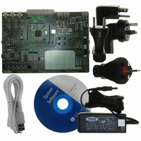
Manufacturer Part Number
EVB9S12XEP100
Description
BOARD EVAL FOR MC9S12XEP100
Manufacturer
Freescale Semiconductor
Type
MCUr
Datasheet
1.EVB9S12XEP100.pdf
(1328 pages)
Specifications of EVB9S12XEP100
Contents
Module and Misc Hardware
Processor To Be Evaluated
MC9S12XEP100
Data Bus Width
16 bit
Interface Type
RS-232
Silicon Manufacturer
Freescale
Core Architecture
S12
Core Sub-architecture
S12
Silicon Core Number
MC9S12
Silicon Family Name
S12XE
Rohs Compliant
Yes
For Use With/related Products
MC9S12XEP100
Lead Free Status / RoHS Status
Lead free / RoHS Compliant


18.4.2
Each time-out event can be used to trigger an interrupt service request. For each timer channel, an
individual bit PINTE in the PIT interrupt enable (PITINTE) register exists to enable this feature. If PINTE
is set, an interrupt service is requested whenever the corresponding time-out flag PTF in the PIT time-out
flag (PITTF) register is set. The flag can be cleared by writing a one to the flag bit.
18.4.3
The PIT module contains four hardware trigger signal lines PITTRIG[3:0], one for each timer channel.
These signals can be connected on SoC level to peripheral modules enabling e.g. periodic ATD conversion
(please refer to the device overview for the mapping of PITTRIG[3:0] signals to peripheral modules).
Whenever a timer channel time-out is reached, the corresponding PTF flag is set and the corresponding
trigger signal PITTRIG triggers a rising edge. The trigger feature requires a minimum time-out period of
two bus clock cycles because the trigger is asserted high for at least one bus clock cycle. For load register
values PITLD = 0x0001 and PITMTLD = 0x0002 the flag setting, trigger timing and a restart with force
load is shown in
18.5
18.5.1
Set the configuration registers before the PITE bit in the PITCFLMT register is set. Before PITE is set, the
configuration registers can be written in arbitrary order.
18.5.2
When the PITCE register bits, the PITINTE register bits or the PITE bit in the PITCFLMT register are
cleared, the corresponding PIT interrupt flags are cleared. In case of a pending PIT interrupt request, a
spurious interrupt can be generated. Two strategies, which avoid spurious interrupts, are recommended:
18.5.3
A flag is cleared by writing a one to the flag bit. Always use store or move instructions to write a one in
certain bit positions. Do not use the BSET instructions. Do not use any C-constructs that compile to BSET
instructions. “BSET flag_register, #mask” must not be used for flag clearing because BSET is a read-
Freescale Semiconductor
Because of an order from the United States International Trade Commission, BGA-packaged product lines and partnumbers
indicated here currently are not available from Freescale for import or sale in the United States prior to September 2010
1. Reset the PIT interrupt flags only in an ISR. When entering the ISR, the I mask bit in the CCR is
2. After setting the I mask bit with the SEI instruction, the PIT interrupt flags can be cleared. Then
set automatically. The I mask bit must not be cleared before the PIT interrupt flags are cleared.
clear the I mask bit with the CLI instruction to re-enable interrupts.
Initialization
Interrupt Interface
Hardware Trigger
Startup
Shutdown
Flag Clearing
Be careful when resetting the PITE, PINTE or PITCE bits in case of pending
PIT interrupt requests, to avoid spurious interrupt requests.
Figure
18-20.
MC9S12XE-Family Reference Manual Rev. 1.23
NOTE
Chapter 18 Periodic Interrupt Timer (S12PIT24B4CV2)
691
Related parts for EVB9S12XEP100
Image
Part Number
Description
Manufacturer
Datasheet
Request
R

Part Number:
Description:
Manufacturer:
Freescale Semiconductor, Inc
Datasheet:
Part Number:
Description:
Manufacturer:
Freescale Semiconductor, Inc
Datasheet:
Part Number:
Description:
Manufacturer:
Freescale Semiconductor, Inc
Datasheet:
Part Number:
Description:
Manufacturer:
Freescale Semiconductor, Inc
Datasheet:
Part Number:
Description:
Manufacturer:
Freescale Semiconductor, Inc
Datasheet:
Part Number:
Description:
Manufacturer:
Freescale Semiconductor, Inc
Datasheet:
Part Number:
Description:
Manufacturer:
Freescale Semiconductor, Inc
Datasheet:
Part Number:
Description:
Manufacturer:
Freescale Semiconductor, Inc
Datasheet:
Part Number:
Description:
Manufacturer:
Freescale Semiconductor, Inc
Datasheet:
Part Number:
Description:
Manufacturer:
Freescale Semiconductor, Inc
Datasheet:
Part Number:
Description:
Manufacturer:
Freescale Semiconductor, Inc
Datasheet:
Part Number:
Description:
Manufacturer:
Freescale Semiconductor, Inc
Datasheet:
Part Number:
Description:
Manufacturer:
Freescale Semiconductor, Inc
Datasheet:
Part Number:
Description:
Manufacturer:
Freescale Semiconductor, Inc
Datasheet:
Part Number:
Description:
Manufacturer:
Freescale Semiconductor, Inc
Datasheet: