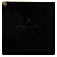
MPC564MZP56 Freescale Semiconductor, MPC564MZP56 Datasheet - Page 213

MPC564MZP56
Manufacturer Part Number
MPC564MZP56
Description
IC MCU 512K FLASH 56MHZ 388-BGA
Manufacturer
Freescale Semiconductor
Series
MPC5xxr
Specifications of MPC564MZP56
Core Processor
PowerPC
Core Size
32-Bit
Speed
56MHz
Connectivity
CAN, EBI/EMI, SCI, SPI, UART/USART
Peripherals
POR, PWM, WDT
Number Of I /o
56
Program Memory Size
512KB (512K x 8)
Program Memory Type
FLASH
Ram Size
32K x 8
Voltage - Supply (vcc/vdd)
2.5 V ~ 2.7 V
Data Converters
A/D 32x10b
Oscillator Type
External
Operating Temperature
-40°C ~ 125°C
Package / Case
388-BGA
Core
PowerPC
Processor Series
MPC5xx
Data Bus Width
32 bit
Maximum Clock Frequency
56 MHz
Data Ram Size
32 KB
On-chip Adc
Yes
Number Of Programmable I/os
56
Number Of Timers
2
Operating Supply Voltage
0 V to 5 V
Mounting Style
SMD/SMT
A/d Bit Size
10 bit
A/d Channels Available
32
Height
1.95 mm
Interface Type
CAN, JTAG, QSPI, SCI, SPI, UART
Length
27 mm
Maximum Operating Temperature
+ 125 C
Minimum Operating Temperature
- 40 C
Supply Voltage (max)
2.7 V, 5.25 V
Supply Voltage (min)
2.5 V, 4.75 V
Width
27 mm
For Use With
MPC564EVB - KIT EVAL FOR MPC561/562/563/564
Lead Free Status / RoHS Status
Contains lead / RoHS non-compliant
Eeprom Size
-
Lead Free Status / Rohs Status
No RoHS Version Available
Available stocks
Company
Part Number
Manufacturer
Quantity
Price
Company:
Part Number:
MPC564MZP56
Manufacturer:
FREESCAL
Quantity:
364
Company:
Part Number:
MPC564MZP56
Manufacturer:
Freescale Semiconductor
Quantity:
10 000
Part Number:
MPC564MZP56
Manufacturer:
FREESCALE
Quantity:
20 000
Company:
Part Number:
MPC564MZP56R2
Manufacturer:
Freescale Semiconductor
Quantity:
10 000
- Current page: 213 of 1420
- Download datasheet (11Mb)
4.2.6
When the MPC561/MPC563 RCPU core is in debug mode, the BBC initiates non-burstable access to the
debug port and ICDU is bypassed (i.e., instructions transmitted to the debug port must be non-compressed
regardless of RCPU MSR[DCMPEN] bit state).
4.3
The BBC is able to relocate the exception addresses of the RCPU. The relocation feature always maps the
exception addresses into the internal memory space of the MPC561/MPC563. See
is important in multi-MPC561/MPC563 systems, where, although the memory map in some was shifted
to not be on the lower 4 Mbytes, their RCPU cores can still access their own exception handlers in their
internal Flash in spite of several RCPUs issuing the same exception addresses.
The relocation also saves wasted space between the exception table entries in the case where each
exception entry contained only a branch instruction to the exception routine, which is located elsewhere.
The exception vector table may be programmed to be located in four places in the MPC561/MPC563
internal memory space.
The exception table relocation is supported in both decompression on and decompression off operation
modes.
The RESET routine vector is relocated differently in decompression on and in decompression off modes.
This feature may be used by a software code compression tool to guarantee that a vocabulary table
initialization routine is always executed before application code is running.
Freescale Semiconductor
Exception Table Relocation (ETR)
Debug Operation Mode
Because HRESET resets the EN_COMP bit and the EXC_COMP bit but
SRESET does not, there may be different behavior between HRESET and
SRESET when both EN_COMP and EXC_COMP are set. Special care must
be taken to ensure operation in a known mode whenever reset occurs. The
reset states of these bits are determined by reset configuration words. The
location of the reset vector is dependent on the value of the MSR[IP] bit in
the RCPU. If MSR[IP] is set, the exception table relocation feature can be
used. See
Section 4.3.1, “ETR
MPC561/MPC563 Reference Manual, Rev. 1.2
Operation.”
NOTE
Burst Buffer Controller 2 Module
Figure
4-2. This feature
4-7
Related parts for MPC564MZP56
Image
Part Number
Description
Manufacturer
Datasheet
Request
R

Part Number:
Description:
MPC5 1K0 5%
Manufacturer:
TE Connectivity
Datasheet:

Part Number:
Description:
MPC5 500R 5%
Manufacturer:
TE Connectivity
Datasheet:

Part Number:
Description:
MPC5 5K0 5%
Manufacturer:
Tyco Electronics
Datasheet:

Part Number:
Description:
MPC5 5R0 5%
Manufacturer:
Tyco Electronics
Datasheet:

Part Number:
Description:
MPC5 50K 5%
Manufacturer:
Tyco Electronics
Datasheet:

Part Number:
Description:
MPC5 1R0 5%
Manufacturer:
Tyco Electronics
Datasheet:
Part Number:
Description:
Manufacturer:
Freescale Semiconductor, Inc
Datasheet:
Part Number:
Description:
Manufacturer:
Freescale Semiconductor, Inc
Datasheet:
Part Number:
Description:
Manufacturer:
Freescale Semiconductor, Inc
Datasheet:
Part Number:
Description:
Manufacturer:
Freescale Semiconductor, Inc
Datasheet:
Part Number:
Description:
Manufacturer:
Freescale Semiconductor, Inc
Datasheet:


