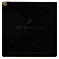
MPC564MZP56 Freescale Semiconductor, MPC564MZP56 Datasheet - Page 801

MPC564MZP56
Manufacturer Part Number
MPC564MZP56
Description
IC MCU 512K FLASH 56MHZ 388-BGA
Manufacturer
Freescale Semiconductor
Series
MPC5xxr
Specifications of MPC564MZP56
Core Processor
PowerPC
Core Size
32-Bit
Speed
56MHz
Connectivity
CAN, EBI/EMI, SCI, SPI, UART/USART
Peripherals
POR, PWM, WDT
Number Of I /o
56
Program Memory Size
512KB (512K x 8)
Program Memory Type
FLASH
Ram Size
32K x 8
Voltage - Supply (vcc/vdd)
2.5 V ~ 2.7 V
Data Converters
A/D 32x10b
Oscillator Type
External
Operating Temperature
-40°C ~ 125°C
Package / Case
388-BGA
Core
PowerPC
Processor Series
MPC5xx
Data Bus Width
32 bit
Maximum Clock Frequency
56 MHz
Data Ram Size
32 KB
On-chip Adc
Yes
Number Of Programmable I/os
56
Number Of Timers
2
Operating Supply Voltage
0 V to 5 V
Mounting Style
SMD/SMT
A/d Bit Size
10 bit
A/d Channels Available
32
Height
1.95 mm
Interface Type
CAN, JTAG, QSPI, SCI, SPI, UART
Length
27 mm
Maximum Operating Temperature
+ 125 C
Minimum Operating Temperature
- 40 C
Supply Voltage (max)
2.7 V, 5.25 V
Supply Voltage (min)
2.5 V, 4.75 V
Width
27 mm
For Use With
MPC564EVB - KIT EVAL FOR MPC561/562/563/564
Lead Free Status / RoHS Status
Contains lead / RoHS non-compliant
Eeprom Size
-
Lead Free Status / Rohs Status
No RoHS Version Available
Available stocks
Company
Part Number
Manufacturer
Quantity
Price
Company:
Part Number:
MPC564MZP56
Manufacturer:
FREESCAL
Quantity:
364
Company:
Part Number:
MPC564MZP56
Manufacturer:
Freescale Semiconductor
Quantity:
10 000
Part Number:
MPC564MZP56
Manufacturer:
FREESCALE
Quantity:
20 000
Company:
Part Number:
MPC564MZP56R2
Manufacturer:
Freescale Semiconductor
Quantity:
10 000
- Current page: 801 of 1420
- Download datasheet (11Mb)
17.12.5 Interrupt Control Section (ICS)
The interrupt control section delivers the interrupt level to the CPU. The interrupt control section adapts
the characteristics of the MIOB request bus to the characteristics of the interrupt structure of the IMB3.
When at least one of the flags is set on an enabled level, the ICS receives a signal from the corresponding
IRQ pending register. This signal is the result of a logical “OR” between all the bits of the IRQ pending
register.
The signal received from the IRQ pending register is associated with the interrupt level register within the
ICS. This level is coded on five bits in this register: three bits represent one of eight levels and the two
other represent the four time multiplex slots. According to this level, the ICS sets the correct IRQ[7:0] lines
with the correct ILBS[1:0] time multiplex lines on the peripheral bus. The CPU is then informed as to
which of the thirty-two interrupt levels is requested.
Based on the interrupt level requested, the software must determine which submodule requested the
interrupt. The software may use a find-first-one type of instruction to determine, in the concerned MIRSM,
which of the bits is set. The CPU can then serve the requested interrupt.
17.12.6 MBISM Interrupt Registers
Table 17-41
17.12.6.1 MIOS14 Interrupt Level Register 0 (MIOS14LVL0)
This register contains the interrupt level that applies to the submodules numbers 15 to zero.
Freescale Semiconductor
SRESET
10:15
Bits
Field
7:9
Addr
shows the MBISM interrupt registers.
MSB
IRP24:22 Pending Bits — MMCSM pending bits [24:22]
IRP21:16 Pending Bits — PWMSM pending bits [21:16]
0
Name
0x30 6C30
0x30 6C70
Address
1
Figure 17-41. MIOS14 Interrupt Level Register 0 (MIOS14LVL0)
—
Table 17-40. MIOS14RPR1 Bit Descriptions (continued)
2
Table 17-41. MBISM Interrupt Registers Address Map
MIOS14 Interrupt Level Register 0 (MIOS14LVL0)
See
MIOS14 Interrupt Level Register 1 (MIOS14LVL1)
See
3
MPC561/MPC563 Reference Manual, Rev. 1.2
Table 17-42
Table 17-43
4
5
for bit descriptions.
for bit descriptions.
LVL
0000_0000_0000_0000
6
0x30 6C30
7
Register
Description
8
TM
9
10
Modular Input/Output Subsystem (MIOS14)
11
12
—
13
14
LSB
15
17-69
Related parts for MPC564MZP56
Image
Part Number
Description
Manufacturer
Datasheet
Request
R

Part Number:
Description:
MPC5 1K0 5%
Manufacturer:
TE Connectivity
Datasheet:

Part Number:
Description:
MPC5 500R 5%
Manufacturer:
TE Connectivity
Datasheet:

Part Number:
Description:
MPC5 5K0 5%
Manufacturer:
Tyco Electronics
Datasheet:

Part Number:
Description:
MPC5 5R0 5%
Manufacturer:
Tyco Electronics
Datasheet:

Part Number:
Description:
MPC5 50K 5%
Manufacturer:
Tyco Electronics
Datasheet:

Part Number:
Description:
MPC5 1R0 5%
Manufacturer:
Tyco Electronics
Datasheet:
Part Number:
Description:
Manufacturer:
Freescale Semiconductor, Inc
Datasheet:
Part Number:
Description:
Manufacturer:
Freescale Semiconductor, Inc
Datasheet:
Part Number:
Description:
Manufacturer:
Freescale Semiconductor, Inc
Datasheet:
Part Number:
Description:
Manufacturer:
Freescale Semiconductor, Inc
Datasheet:
Part Number:
Description:
Manufacturer:
Freescale Semiconductor, Inc
Datasheet:


