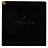
MPC564MZP56 Freescale Semiconductor, MPC564MZP56 Datasheet - Page 291

MPC564MZP56
Manufacturer Part Number
MPC564MZP56
Description
IC MCU 512K FLASH 56MHZ 388-BGA
Manufacturer
Freescale Semiconductor
Series
MPC5xxr
Specifications of MPC564MZP56
Core Processor
PowerPC
Core Size
32-Bit
Speed
56MHz
Connectivity
CAN, EBI/EMI, SCI, SPI, UART/USART
Peripherals
POR, PWM, WDT
Number Of I /o
56
Program Memory Size
512KB (512K x 8)
Program Memory Type
FLASH
Ram Size
32K x 8
Voltage - Supply (vcc/vdd)
2.5 V ~ 2.7 V
Data Converters
A/D 32x10b
Oscillator Type
External
Operating Temperature
-40°C ~ 125°C
Package / Case
388-BGA
Core
PowerPC
Processor Series
MPC5xx
Data Bus Width
32 bit
Maximum Clock Frequency
56 MHz
Data Ram Size
32 KB
On-chip Adc
Yes
Number Of Programmable I/os
56
Number Of Timers
2
Operating Supply Voltage
0 V to 5 V
Mounting Style
SMD/SMT
A/d Bit Size
10 bit
A/d Channels Available
32
Height
1.95 mm
Interface Type
CAN, JTAG, QSPI, SCI, SPI, UART
Length
27 mm
Maximum Operating Temperature
+ 125 C
Minimum Operating Temperature
- 40 C
Supply Voltage (max)
2.7 V, 5.25 V
Supply Voltage (min)
2.5 V, 4.75 V
Width
27 mm
For Use With
MPC564EVB - KIT EVAL FOR MPC561/562/563/564
Lead Free Status / RoHS Status
Contains lead / RoHS non-compliant
Eeprom Size
-
Lead Free Status / Rohs Status
No RoHS Version Available
Available stocks
Company
Part Number
Manufacturer
Quantity
Price
Company:
Part Number:
MPC564MZP56
Manufacturer:
FREESCAL
Quantity:
364
Company:
Part Number:
MPC564MZP56
Manufacturer:
Freescale Semiconductor
Quantity:
10 000
Part Number:
MPC564MZP56
Manufacturer:
FREESCALE
Quantity:
20 000
Company:
Part Number:
MPC564MZP56R2
Manufacturer:
Freescale Semiconductor
Quantity:
10 000
- Current page: 291 of 1420
- Download datasheet (11Mb)
use the MPC561/MPC563 CLKOUT signal. This source of reset can be optionally asserted if the LOLRE
bit in the PLL, low-power, and reset control register (PLPRCR) is set. The enabled PLL loss of lock event
generates an internal hard reset sequence. Refer to
information on loss of PLL lock.
7.1.5
If the system clock is switched to the backup clock or switched from backup clock to another clock source
an internal hard reset sequence is generated. Refer to
7.1.6
When the MPC561/MPC563 software watchdog counts to zero, a software watchdog reset is asserted. The
enabled software watchdog event generates an internal hard reset sequence.
7.1.7
When the RCPU enters a checkstop state, and the checkstop reset is enabled (the CSR bit in the PLPRCR
is set), a checkstop reset is asserted. The enabled checkstop event generates an internal hard reset sequence.
Refer to the RCPU Reference Manual for more information.
7.1.8
When the development port receives a hard reset request from the development tool, an internal hard reset
sequence is generated. In this case the development tool must reconfigure the debug port. Refer to
Chapter 23, “Development
7.1.9
When the development port receives a soft reset request from the development tool, an internal soft reset
sequence is generated. In this case the development tool must reconfigure the debug port. Refer to
Chapter 23, “Development
7.1.10
When the JTAG logic asserts the JTAG soft reset signal, an internal soft reset sequence is generated. Refer
to
7.1.11
When locked bits in the PLPRCR register are changed, an internal hard reset sequence is generated. Refer
to
7.2
Table 7-1
Freescale Semiconductor
Chapter 25, “IEEE 1149.1-Compliant Interface
Chapter 8, “Clocks and Power
Reset Actions Summary
summarizes the action taken for each reset.
On-Chip Clock Switch
Software Watchdog Reset
Checkstop Reset
Debug Port Hard Reset
Debug Port Soft Reset
JTAG Reset
ILBC Illegal Bit Change
Support,” for more information.
Support,” for more information.
MPC561/MPC563 Reference Manual, Rev. 1.2
Control.”
(JTAG),” for more information.
Chapter 8, “Clocks and Power
Chapter 8, “Clocks and Power
Control,” for more
Control.”
Reset
7-3
Related parts for MPC564MZP56
Image
Part Number
Description
Manufacturer
Datasheet
Request
R

Part Number:
Description:
MPC5 1K0 5%
Manufacturer:
TE Connectivity
Datasheet:

Part Number:
Description:
MPC5 500R 5%
Manufacturer:
TE Connectivity
Datasheet:

Part Number:
Description:
MPC5 5K0 5%
Manufacturer:
Tyco Electronics
Datasheet:

Part Number:
Description:
MPC5 5R0 5%
Manufacturer:
Tyco Electronics
Datasheet:

Part Number:
Description:
MPC5 50K 5%
Manufacturer:
Tyco Electronics
Datasheet:

Part Number:
Description:
MPC5 1R0 5%
Manufacturer:
Tyco Electronics
Datasheet:
Part Number:
Description:
Manufacturer:
Freescale Semiconductor, Inc
Datasheet:
Part Number:
Description:
Manufacturer:
Freescale Semiconductor, Inc
Datasheet:
Part Number:
Description:
Manufacturer:
Freescale Semiconductor, Inc
Datasheet:
Part Number:
Description:
Manufacturer:
Freescale Semiconductor, Inc
Datasheet:
Part Number:
Description:
Manufacturer:
Freescale Semiconductor, Inc
Datasheet:


