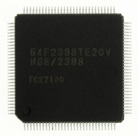
HD64F2145BTE20 Renesas Electronics America, HD64F2145BTE20 Datasheet - Page 332

HD64F2145BTE20
Manufacturer Part Number
HD64F2145BTE20
Description
IC H8S MCU FLASH 256K 100-QFP
Manufacturer
Renesas Electronics America
Series
H8® H8S/2100r
Specifications of HD64F2145BTE20
Core Processor
H8S/2000
Core Size
16-Bit
Speed
20MHz
Connectivity
I²C, IrDA, SCI, X-Bus
Peripherals
PWM, WDT
Number Of I /o
74
Program Memory Size
256KB (256K x 8)
Program Memory Type
FLASH
Ram Size
8K x 8
Voltage - Supply (vcc/vdd)
4.5 V ~ 5.5 V
Data Converters
A/D 8x10b; D/A 2x8b
Oscillator Type
Internal
Operating Temperature
-20°C ~ 75°C
Package / Case
100-TQFP, 100-VQFP
Lead Free Status / RoHS Status
Contains lead / RoHS non-compliant
Eeprom Size
-
- Current page: 332 of 847
- Download datasheet (5Mb)
Section 11 16-Bit Free-Running Timer (FRT)
11.5.6
The input capture flag, ICFA, ICFB, ICFC, or ICFD, is set to 1 by the input capture signal. The
FRC value is simultaneously transferred to the corresponding input capture register (ICRA, ICRB,
ICRC, or ICRD). Figure 11.11 shows the timing of setting the ICFA to ICFD flag.
11.5.7
The output compare flag, OCFA or OCFB, is set to 1 by a compare-match signal generated when
the FRC value matches the OCRA or OCRB value. This compare-match signal is generated at the
last state in which the two values match, just before FRC increments to a new value. When the
FRC and OCRA or OCRB value match, the compare-match signal is not generated until the next
cycle of the clock source. Figure 11.12 shows the timing of setting the OCFA or OCFB flag.
Rev. 3.00 Mar 21, 2006 page 276 of 788
REJ09B0300-0300
Figure 11.11 Timing of Input Capture Flag (ICFA, ICFB, ICFC, or ICFD) Setting
Input capture
signal
ICFA to ICFD
FRC
ICRA to ICRD
Timing of Input Capture Flag (ICF) Setting
Timing of Output Compare Flag (OCF) setting
N
N
Related parts for HD64F2145BTE20
Image
Part Number
Description
Manufacturer
Datasheet
Request
R

Part Number:
Description:
KIT STARTER FOR M16C/29
Manufacturer:
Renesas Electronics America
Datasheet:

Part Number:
Description:
KIT STARTER FOR R8C/2D
Manufacturer:
Renesas Electronics America
Datasheet:

Part Number:
Description:
R0K33062P STARTER KIT
Manufacturer:
Renesas Electronics America
Datasheet:

Part Number:
Description:
KIT STARTER FOR R8C/23 E8A
Manufacturer:
Renesas Electronics America
Datasheet:

Part Number:
Description:
KIT STARTER FOR R8C/25
Manufacturer:
Renesas Electronics America
Datasheet:

Part Number:
Description:
KIT STARTER H8S2456 SHARPE DSPLY
Manufacturer:
Renesas Electronics America
Datasheet:

Part Number:
Description:
KIT STARTER FOR R8C38C
Manufacturer:
Renesas Electronics America
Datasheet:

Part Number:
Description:
KIT STARTER FOR R8C35C
Manufacturer:
Renesas Electronics America
Datasheet:

Part Number:
Description:
KIT STARTER FOR R8CL3AC+LCD APPS
Manufacturer:
Renesas Electronics America
Datasheet:

Part Number:
Description:
KIT STARTER FOR RX610
Manufacturer:
Renesas Electronics America
Datasheet:

Part Number:
Description:
KIT STARTER FOR R32C/118
Manufacturer:
Renesas Electronics America
Datasheet:

Part Number:
Description:
KIT DEV RSK-R8C/26-29
Manufacturer:
Renesas Electronics America
Datasheet:

Part Number:
Description:
KIT STARTER FOR SH7124
Manufacturer:
Renesas Electronics America
Datasheet:

Part Number:
Description:
KIT STARTER FOR H8SX/1622
Manufacturer:
Renesas Electronics America
Datasheet:

Part Number:
Description:
KIT DEV FOR SH7203
Manufacturer:
Renesas Electronics America
Datasheet:


