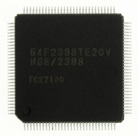
HD64F2145BTE20 Renesas Electronics America, HD64F2145BTE20 Datasheet - Page 694

HD64F2145BTE20
Manufacturer Part Number
HD64F2145BTE20
Description
IC H8S MCU FLASH 256K 100-QFP
Manufacturer
Renesas Electronics America
Series
H8® H8S/2100r
Specifications of HD64F2145BTE20
Core Processor
H8S/2000
Core Size
16-Bit
Speed
20MHz
Connectivity
I²C, IrDA, SCI, X-Bus
Peripherals
PWM, WDT
Number Of I /o
74
Program Memory Size
256KB (256K x 8)
Program Memory Type
FLASH
Ram Size
8K x 8
Voltage - Supply (vcc/vdd)
4.5 V ~ 5.5 V
Data Converters
A/D 8x10b; D/A 2x8b
Oscillator Type
Internal
Operating Temperature
-20°C ~ 75°C
Package / Case
100-TQFP, 100-VQFP
Lead Free Status / RoHS Status
Contains lead / RoHS non-compliant
Eeprom Size
-
- Current page: 694 of 847
- Download datasheet (5Mb)
Section 24 Clock Pulse Generator
24.4
The bus master clock select circuit selects a clock to supply the bus master with either the system
clock ( ) or medium-speed clock ( /2, /4, /8, /16, or /32) by the SCK2 to SCK0 bits in
SBYCR.
24.5
The subclock input circuit controls subclock input from the EXCL pin.
Inputting the Subclock: To use the subclock, a 32.768-kHz external clock should be input from
the EXCL pin. At this time, the P96DDR bit in P9DDR should be cleared to 0, and the EXCLE bit
in LPWRCR should be set to 1.
Subclock input conditions are shown in table 24.5. When the subclock is not used, subclock input
should not be enabled.
Table 24.5 Subclock Input Conditions
Item
Subclock input pulse width
low level
Subclock input pulse width
high level
Subclock input rising time
Subclock input falling time
Rev. 3.00 Mar 21, 2006 page 638 of 788
REJ09B0300-0300
Bus Master Clock Select Circuit
Subclock Input Circuit
EXCL
t
EXCLr
Symbol
t
t
t
t
Figure 24.7 Subclock Input Timing
EXCLL
EXCLH
EXCLr
EXCLf
t
EXCLH
Min
—
—
—
—
Vcc = 2.7 to 5.5 V
Typ
15.26
15.26
—
—
t
EXCLf
t
EXCLL
Max
—
—
10
10
V
Unit
ns
ns
CC
s
s
× 0.5
Measurement
Condition
Figure 24.7
Related parts for HD64F2145BTE20
Image
Part Number
Description
Manufacturer
Datasheet
Request
R

Part Number:
Description:
KIT STARTER FOR M16C/29
Manufacturer:
Renesas Electronics America
Datasheet:

Part Number:
Description:
KIT STARTER FOR R8C/2D
Manufacturer:
Renesas Electronics America
Datasheet:

Part Number:
Description:
R0K33062P STARTER KIT
Manufacturer:
Renesas Electronics America
Datasheet:

Part Number:
Description:
KIT STARTER FOR R8C/23 E8A
Manufacturer:
Renesas Electronics America
Datasheet:

Part Number:
Description:
KIT STARTER FOR R8C/25
Manufacturer:
Renesas Electronics America
Datasheet:

Part Number:
Description:
KIT STARTER H8S2456 SHARPE DSPLY
Manufacturer:
Renesas Electronics America
Datasheet:

Part Number:
Description:
KIT STARTER FOR R8C38C
Manufacturer:
Renesas Electronics America
Datasheet:

Part Number:
Description:
KIT STARTER FOR R8C35C
Manufacturer:
Renesas Electronics America
Datasheet:

Part Number:
Description:
KIT STARTER FOR R8CL3AC+LCD APPS
Manufacturer:
Renesas Electronics America
Datasheet:

Part Number:
Description:
KIT STARTER FOR RX610
Manufacturer:
Renesas Electronics America
Datasheet:

Part Number:
Description:
KIT STARTER FOR R32C/118
Manufacturer:
Renesas Electronics America
Datasheet:

Part Number:
Description:
KIT DEV RSK-R8C/26-29
Manufacturer:
Renesas Electronics America
Datasheet:

Part Number:
Description:
KIT STARTER FOR SH7124
Manufacturer:
Renesas Electronics America
Datasheet:

Part Number:
Description:
KIT STARTER FOR H8SX/1622
Manufacturer:
Renesas Electronics America
Datasheet:

Part Number:
Description:
KIT DEV FOR SH7203
Manufacturer:
Renesas Electronics America
Datasheet:


