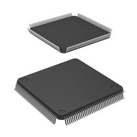
HD64F2676VFC33 Renesas Electronics America, HD64F2676VFC33 Datasheet - Page 26

HD64F2676VFC33
Manufacturer Part Number
HD64F2676VFC33
Description
IC H8S MCU FLASH 256K 144-QFP
Manufacturer
Renesas Electronics America
Series
H8® H8S/2600r
Specifications of HD64F2676VFC33
Core Processor
H8S/2600
Core Size
16-Bit
Speed
33MHz
Connectivity
IrDA, SCI
Peripherals
DMA, POR, PWM, WDT
Number Of I /o
103
Program Memory Size
256KB (256K x 8)
Program Memory Type
FLASH
Ram Size
8K x 8
Voltage - Supply (vcc/vdd)
3 V ~ 3.6 V
Data Converters
A/D 12x10b; D/A 4x8b
Oscillator Type
Internal
Operating Temperature
-20°C ~ 75°C
Package / Case
144-QFP
Lead Free Status / RoHS Status
Contains lead / RoHS non-compliant
Eeprom Size
-
Available stocks
Company
Part Number
Manufacturer
Quantity
Price
Company:
Part Number:
HD64F2676VFC33
Manufacturer:
RENESAS
Quantity:
5 530
Company:
Part Number:
HD64F2676VFC33
Manufacturer:
Renesas Electronics America
Quantity:
10 000
Company:
Part Number:
HD64F2676VFC33V
Manufacturer:
RENESAS
Quantity:
5 530
Company:
Part Number:
HD64F2676VFC33V
Manufacturer:
ROHM
Quantity:
750 000
Part Number:
HD64F2676VFC33V
Manufacturer:
RENESAS/瑞萨
Quantity:
20 000
- Current page: 26 of 981
- Download datasheet (6Mb)
12.4 Operation .......................................................................................................................... 615
12.5 Usage Notes ...................................................................................................................... 625
Section 13 8-Bit Timers (TMR)
13.1 Features ............................................................................................................................. 627
13.2 Input/Output Pins .............................................................................................................. 629
13.3 Register Descriptions ........................................................................................................ 629
13.4 Operation .......................................................................................................................... 636
13.5 Operation Timing.............................................................................................................. 637
13.6 Operation with Cascaded Connection ............................................................................... 641
13.7 Interrupts ........................................................................................................................... 642
13.8 Usage Notes ...................................................................................................................... 643
Rev. 3.00 Mar 17, 2006 page xxiv of l
12.3.5 PPG Output Mode Register (PMR)...................................................................... 613
12.4.1 Output Timing...................................................................................................... 616
12.4.2 Sample Setup Procedure for Normal Pulse Output.............................................. 617
12.4.3 Example of Normal Pulse Output (Example of Five-Phase Pulse Output).......... 618
12.4.4 Non-Overlapping Pulse Output............................................................................ 619
12.4.5 Sample Setup Procedure for Non-Overlapping Pulse Output .............................. 621
12.4.6 Example of Non-Overlapping Pulse Output
12.4.7 Inverted Pulse Output .......................................................................................... 624
12.4.8 Pulse Output Triggered by Input Capture ............................................................ 625
12.5.1 Module Stop Mode Setting .................................................................................. 625
12.5.2 Operation of Pulse Output Pins............................................................................ 625
13.3.1 Timer Counter (TCNT)........................................................................................ 630
13.3.2 Time Constant Register A (TCORA)................................................................... 630
13.3.3 Time Constant Register B (TCORB) ................................................................... 630
13.3.4 Timer Control Register (TCR) ............................................................................. 631
13.3.5 Timer Control/Status Register (TCSR) ................................................................ 633
13.4.1 Pulse Output......................................................................................................... 636
13.5.1 TCNT Incrementation Timing ............................................................................. 637
13.5.2 Timing of CMFA and CMFB Setting when Compare-Match Occurs ................. 638
13.5.3 Timing of Timer Output when Compare-Match Occurs...................................... 639
13.5.4 Timing of Compare Match Clear ......................................................................... 639
13.5.5 Timing of TCNT External Reset.......................................................................... 640
13.5.6 Timing of Overflow Flag (OVF) Setting ............................................................. 640
13.6.1 16-Bit Counter Mode ........................................................................................... 641
13.6.2 Compare Match Count Mode............................................................................... 641
13.7.1 Interrupt Sources and DTC Activation ................................................................ 642
13.7.2 A/D Converter Activation.................................................................................... 642
13.8.1 Contention between TCNT Write and Clear........................................................ 643
(Example of Four-Phase Complementary Non-Overlapping Output).................. 622
...................................................................................... 627
Related parts for HD64F2676VFC33
Image
Part Number
Description
Manufacturer
Datasheet
Request
R

Part Number:
Description:
KIT STARTER FOR M16C/29
Manufacturer:
Renesas Electronics America
Datasheet:

Part Number:
Description:
KIT STARTER FOR R8C/2D
Manufacturer:
Renesas Electronics America
Datasheet:

Part Number:
Description:
R0K33062P STARTER KIT
Manufacturer:
Renesas Electronics America
Datasheet:

Part Number:
Description:
KIT STARTER FOR R8C/23 E8A
Manufacturer:
Renesas Electronics America
Datasheet:

Part Number:
Description:
KIT STARTER FOR R8C/25
Manufacturer:
Renesas Electronics America
Datasheet:

Part Number:
Description:
KIT STARTER H8S2456 SHARPE DSPLY
Manufacturer:
Renesas Electronics America
Datasheet:

Part Number:
Description:
KIT STARTER FOR R8C38C
Manufacturer:
Renesas Electronics America
Datasheet:

Part Number:
Description:
KIT STARTER FOR R8C35C
Manufacturer:
Renesas Electronics America
Datasheet:

Part Number:
Description:
KIT STARTER FOR R8CL3AC+LCD APPS
Manufacturer:
Renesas Electronics America
Datasheet:

Part Number:
Description:
KIT STARTER FOR RX610
Manufacturer:
Renesas Electronics America
Datasheet:

Part Number:
Description:
KIT STARTER FOR R32C/118
Manufacturer:
Renesas Electronics America
Datasheet:

Part Number:
Description:
KIT DEV RSK-R8C/26-29
Manufacturer:
Renesas Electronics America
Datasheet:

Part Number:
Description:
KIT STARTER FOR SH7124
Manufacturer:
Renesas Electronics America
Datasheet:

Part Number:
Description:
KIT STARTER FOR H8SX/1622
Manufacturer:
Renesas Electronics America
Datasheet:

Part Number:
Description:
KIT DEV FOR SH7203
Manufacturer:
Renesas Electronics America
Datasheet:


