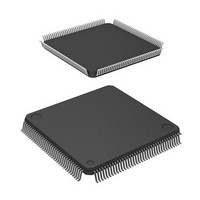
HD64F2676VFC33 Renesas Electronics America, HD64F2676VFC33 Datasheet - Page 29

HD64F2676VFC33
Manufacturer Part Number
HD64F2676VFC33
Description
IC H8S MCU FLASH 256K 144-QFP
Manufacturer
Renesas Electronics America
Series
H8® H8S/2600r
Specifications of HD64F2676VFC33
Core Processor
H8S/2600
Core Size
16-Bit
Speed
33MHz
Connectivity
IrDA, SCI
Peripherals
DMA, POR, PWM, WDT
Number Of I /o
103
Program Memory Size
256KB (256K x 8)
Program Memory Type
FLASH
Ram Size
8K x 8
Voltage - Supply (vcc/vdd)
3 V ~ 3.6 V
Data Converters
A/D 12x10b; D/A 4x8b
Oscillator Type
Internal
Operating Temperature
-20°C ~ 75°C
Package / Case
144-QFP
Lead Free Status / RoHS Status
Contains lead / RoHS non-compliant
Eeprom Size
-
Available stocks
Company
Part Number
Manufacturer
Quantity
Price
Company:
Part Number:
HD64F2676VFC33
Manufacturer:
RENESAS
Quantity:
5 530
Company:
Part Number:
HD64F2676VFC33
Manufacturer:
Renesas Electronics America
Quantity:
10 000
Company:
Part Number:
HD64F2676VFC33V
Manufacturer:
RENESAS
Quantity:
5 530
Company:
Part Number:
HD64F2676VFC33V
Manufacturer:
ROHM
Quantity:
750 000
Part Number:
HD64F2676VFC33V
Manufacturer:
RENESAS/瑞萨
Quantity:
20 000
- Current page: 29 of 981
- Download datasheet (6Mb)
Section 16 A/D Converter
16.1 Features ............................................................................................................................. 741
16.2 Input/Output Pins .............................................................................................................. 743
16.3 Register Descriptions ........................................................................................................ 744
16.4 Operation .......................................................................................................................... 752
16.5 Interrupt Source ................................................................................................................ 756
16.6 A/D Conversion Accuracy Definitions ............................................................................. 757
16.7 Usage Notes ...................................................................................................................... 759
Section 17 D/A Converter
17.1 Features ............................................................................................................................. 763
17.2 Input/Output Pins .............................................................................................................. 765
17.3 Register Descriptions ........................................................................................................ 765
17.4 Operation .......................................................................................................................... 769
17.5 Usage Notes ...................................................................................................................... 770
Section 18 RAM
Section 19 Flash Memory (F-ZTAT Version)
19.1 Features ............................................................................................................................. 773
19.2 Mode Transitions .............................................................................................................. 774
19.3 Block Configuration.......................................................................................................... 778
19.4 Input/Output Pins .............................................................................................................. 781
19.5 Register Descriptions ........................................................................................................ 781
16.3.1 A/D Data Registers A to H (ADDRA to ADDRH).............................................. 744
16.3.2 A/D Control/Status Register (ADCSR) ............................................................... 746
16.3.3 A/D Control Register (ADCR) ............................................................................ 750
16.4.1 Single Mode......................................................................................................... 752
16.4.2 Scan Mode ........................................................................................................... 752
16.4.3 Input Sampling and A/D Conversion Time ......................................................... 753
16.4.4 External Trigger Input Timing............................................................................. 756
16.7.1 Module Stop Mode Setting .................................................................................. 759
16.7.2 Permissible Signal Source Impedance ................................................................. 759
16.7.3 Influences on Absolute Precision......................................................................... 760
16.7.4 Setting Range of Analog Power Supply and Other Pins ...................................... 760
16.7.5 Notes on Board Design ........................................................................................ 760
16.7.6 Notes on Noise Countermeasures ........................................................................ 761
17.3.1 D/A Data Registers 0 to 3 (DADR0 to DADR3) ................................................. 765
17.3.2 D/A Control Registers 01 and 23 (DACR01, DACR23) ..................................... 766
17.5.1 Setting for Module Stop Mode............................................................................. 770
17.5.2 D/A Output Hold Function in Software Standby Mode....................................... 770
.................................................................................................................. 771
................................................................................................. 741
................................................................................................. 763
............................................................ 773
Rev. 3.00 Mar 17, 2006 page xxvii of l
Related parts for HD64F2676VFC33
Image
Part Number
Description
Manufacturer
Datasheet
Request
R

Part Number:
Description:
KIT STARTER FOR M16C/29
Manufacturer:
Renesas Electronics America
Datasheet:

Part Number:
Description:
KIT STARTER FOR R8C/2D
Manufacturer:
Renesas Electronics America
Datasheet:

Part Number:
Description:
R0K33062P STARTER KIT
Manufacturer:
Renesas Electronics America
Datasheet:

Part Number:
Description:
KIT STARTER FOR R8C/23 E8A
Manufacturer:
Renesas Electronics America
Datasheet:

Part Number:
Description:
KIT STARTER FOR R8C/25
Manufacturer:
Renesas Electronics America
Datasheet:

Part Number:
Description:
KIT STARTER H8S2456 SHARPE DSPLY
Manufacturer:
Renesas Electronics America
Datasheet:

Part Number:
Description:
KIT STARTER FOR R8C38C
Manufacturer:
Renesas Electronics America
Datasheet:

Part Number:
Description:
KIT STARTER FOR R8C35C
Manufacturer:
Renesas Electronics America
Datasheet:

Part Number:
Description:
KIT STARTER FOR R8CL3AC+LCD APPS
Manufacturer:
Renesas Electronics America
Datasheet:

Part Number:
Description:
KIT STARTER FOR RX610
Manufacturer:
Renesas Electronics America
Datasheet:

Part Number:
Description:
KIT STARTER FOR R32C/118
Manufacturer:
Renesas Electronics America
Datasheet:

Part Number:
Description:
KIT DEV RSK-R8C/26-29
Manufacturer:
Renesas Electronics America
Datasheet:

Part Number:
Description:
KIT STARTER FOR SH7124
Manufacturer:
Renesas Electronics America
Datasheet:

Part Number:
Description:
KIT STARTER FOR H8SX/1622
Manufacturer:
Renesas Electronics America
Datasheet:

Part Number:
Description:
KIT DEV FOR SH7203
Manufacturer:
Renesas Electronics America
Datasheet:


