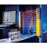
F39-EU1E Omron, F39-EU1E Datasheet - Page 321

F39-EU1E
Manufacturer Part Number
F39-EU1E
Description
F3S-B OPTIONAL PROGRAMMING KIT
Manufacturer
Omron
Datasheet
1.F39-EU1E.pdf
(865 pages)
Specifications of F39-EU1E
Leaded Process Compatible
No
Peak Reflow Compatible (260 C)
No
Light Curtain Type
Safety
Lead Free Status / RoHS Status
Contains lead / RoHS non-compliant
Lead Free Status / RoHS Status
Contains lead / RoHS non-compliant
- Current page: 321 of 865
- Download datasheet (35Mb)
Courtesy of Steven Engineering, Inc.-230 Ryan Way, South San Francisco, CA 94080-6370-Main Office: (650) 588-9200-Outside Local Area: (800) 258-9200-www.stevenengineering.com
Note: Unless otherwise specified, a tolerance of 0.4 mm applies to all dimensions.
Note:
Top Plunger
D4B-@@70N
Coil Spring (Non-directional)
D4B-@@81N
Operating characteristics
Operating force
Release force
Pretravel
Overtravel
Movement differential
Direct opening travel
Direct opening force
Total travel
Free position
Operating position
Operating characteristics
Operating force
Pretravel
* Be sure to adjust the dog to within 40 mm
from the top end of the coil spring.
Unless otherwise specified, a tolerance of 0.4 mm applies to all dimensions.
60
203.5
8
±0.2
±1.2
http://www.ia.omron.com/
18.2 dia.
60
29.1
30
40
8
±0.2
±0.2
5.3
+1
0
Stainless steel coil spring
OF max.
RF min.
PT max.
PT (2nd) *1 *3
OT min.
MD max. *2
DOT min. *4
DOF min. *4
TT *3
FP max.
OP
30
40
Two, 5.3-dia.
mounting holes
Two, M4 × 12 cover
mounting screws
OF max.
PT max.
OP
PT
±0.2
5.3
+1
0
7.3
Stainless steel
plunger
Seal cap
Two, M4 × 12 cover
mounting screws
Two, 5.3-dia.
mounting holes
Four, M3.5 × 7
mounting screws
Mechanically speaking, these
models are general limit switches
and not safety limit switches.
7.3
Cover
Model
Model
The Switch can be
actuated in any
direction except to
the axis center.
9.2 dia.
Cover
43
31.5
1.47 N
15°
18.63 N
1.96 N
2 mm
(3 mm)
5 mm
1 mm
3.2 mm
49.03 N
(7 mm)
38 mm
35±1 mm
16
15
D4B-@@81N
D4B-@@70N
15.7
Four, M3.5 × 24.5
head
mounting screws
Conduit opening
43
31.5
74
16
15
6.6 dia.
20
77
(40) *
Conduit
opening
74
97
2.7
77
1.47 N
15°
18.63 N
1.96 N
2 mm
(3 mm)
5 mm
1 mm
3.2 mm
49.03N
(7 mm)
51 mm
48±1 mm
D4B-@@87N
Top Roller Plunger
D4B-@@71N
Plastic Rod (Non-directional)
D4B-@@87N
D4B-@@71N
* Be sure to adjust the dog to within 40 mm
from the top end of the plastic rod.
(c)Copyright OMRON Corporation 2007 All Rights Reserved.
203.5
60
±0.2
8
12.7 dia. × 4.8
stainless steel roller
±1.2
Note: Variation occurs in the simultaneity of
60
Note: Variation occurs in the simultaneity of
*1. Only for slow-action models.
*2. Only for snap-action models.
*3. Reference values.
*4. Must be provided to ensure safe
18.2 dia.
29.1
±0.2
8
30
40
operation.
±0.2
5.3
+1
contact opening/closing operations of
2NC contacts. Check contact
operation.
0
contact opening/closing operations of
2NC contacts. Check contact
operation.
30
40
±0.2
5.3
Two, 5.3-dia.
mounting holes
Two, M4 × 12 cover
mounting screws
+1
0
PT
OP
Plastic rod
7.3
Seal cap
Mechanically speaking, these
models are general limit switches
and not safety limit switches.
Four, M3.5 × 7
head mounting
screws
Two, M4 × 12 cover
mounting screws
Two, 5.3-dia.
mounting holes
7.3
Cover
The Switch can be
actuated in any
direction except to
the axis center.
9.2 dia.
Cover
43
31.5
16
15
15.7
43
D4B-@N
31.5
Conduit opening
Four, M3.5 × 24.5
head
mounting screws
16
15
74
6.6 dia.
(40) *
Conduit
opening
20
77
74
97
2.7
77
9
Related parts for F39-EU1E
Image
Part Number
Description
Manufacturer
Datasheet
Request
R

Part Number:
Description:
Pair Of Flat Mounting Brackets (transmitter & Receiver)
Manufacturer:
Omron

Part Number:
Description:
Pair Of Protective Shrouds (transmitter & Receiver)
Manufacturer:
Omron

Part Number:
Description:
G6S-2GLow Signal Relay
Manufacturer:
Omron Corporation
Datasheet:

Part Number:
Description:
Compact, Low-cost, SSR Switching 5 to 20 A
Manufacturer:
Omron Corporation
Datasheet:

Part Number:
Description:
Manufacturer:
Omron Corporation
Datasheet:


