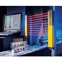
F39-EU1E Omron, F39-EU1E Datasheet - Page 800

F39-EU1E
Manufacturer Part Number
F39-EU1E
Description
F3S-B OPTIONAL PROGRAMMING KIT
Manufacturer
Omron
Datasheet
1.F39-EU1E.pdf
(865 pages)
Specifications of F39-EU1E
Leaded Process Compatible
No
Peak Reflow Compatible (260 C)
No
Light Curtain Type
Safety
Lead Free Status / RoHS Status
Contains lead / RoHS non-compliant
Lead Free Status / RoHS Status
Contains lead / RoHS non-compliant
- Current page: 800 of 865
- Download datasheet (35Mb)
Courtesy of Steven Engineering, Inc.-230 Ryan Way, South San Francisco, CA 94080-6370-Main Office: (650) 588-9200-Outside Local Area: (800) 258-9200-www.stevenengineering.com
Dimensions
Main Unit
F3SN-A@@@P25SS-@@
Dimensions can be calculated for each model by using the following equations.
Note: If value F obtained from the above equation is not used, set F to 670 mm or less.
Mounting Precautions
Note: 1. The mounting bracket (3) (see Mounting Brackets (Intermediate)) is shown on the left-hand side of the Sensor as an example. If the
Dimension C1 (protective height): 4 digits in the model name
Dimension A = C1 + 64
Dimension B = C1 + 32
Dimension D = 18.5
Dimension E = C1 - 37
Dimension F = Refer to the table right.
2. When using the cable bent, use a minimum bending radius of R = 36 mm. Fig. A shows an example when using a Cable with a Straight
Fig. A
mounting bracket (3) is on the right-hand side of the Sensor, then the mounting holes must also be on the right-hand side.
Connector. Fig. B shows the dimensions when using a Cable with a Right-angle Connector.
Connector Cable
http://www.ia.omron.com/
R36 mm
80 mm min.
Connector Cable
M5 up-set hexagon bolt
with Philips driver slot
Two, mounting holes
Four, mounting holes
(41.8)
Two, mounting brackets
Two , mounting holes
Two, mounting holes
38
Intermediate
bracket
15
9.25
28
27
22
5.5
6.5 dia.
11
30
5.5
13.5
R36mm
20
30
80 mm min.
6.5 dia.
2
16.9
8
F
16
(16)
B
to 0640
0641 to 1280
1281 to 1822
M12 waterproof connector
Fig. B
43 mm max.
Protective height
A
(Protective height)
(c)Copyright OMRON Corporation 2007 All Rights Reserved.
C1
(C1)
11
11
D
E
27
Beam
32
1
Connector Cable
Number of intermediate
0
1
2
30
mounting brackets
45
15
Two, M5
Four, M5
22
Mounting screw holes
F3SN-A@SS
20
---
F = B/2
F = B/3
Dimension F
Two, M5
(See note.)
(Unit: mm)
F
B
11
Related parts for F39-EU1E
Image
Part Number
Description
Manufacturer
Datasheet
Request
R

Part Number:
Description:
Pair Of Flat Mounting Brackets (transmitter & Receiver)
Manufacturer:
Omron

Part Number:
Description:
Pair Of Protective Shrouds (transmitter & Receiver)
Manufacturer:
Omron

Part Number:
Description:
G6S-2GLow Signal Relay
Manufacturer:
Omron Corporation
Datasheet:

Part Number:
Description:
Compact, Low-cost, SSR Switching 5 to 20 A
Manufacturer:
Omron Corporation
Datasheet:

Part Number:
Description:
Manufacturer:
Omron Corporation
Datasheet:


