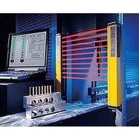
F39-EU1E Omron, F39-EU1E Datasheet - Page 846

F39-EU1E
Manufacturer Part Number
F39-EU1E
Description
F3S-B OPTIONAL PROGRAMMING KIT
Manufacturer
Omron
Datasheet
1.F39-EU1E.pdf
(865 pages)
Specifications of F39-EU1E
Leaded Process Compatible
No
Peak Reflow Compatible (260 C)
No
Light Curtain Type
Safety
Lead Free Status / RoHS Status
Contains lead / RoHS non-compliant
Lead Free Status / RoHS Status
Contains lead / RoHS non-compliant
- Current page: 846 of 865
- Download datasheet (35Mb)
Courtesy of Steven Engineering, Inc.-230 Ryan Way, South San Francisco, CA 94080-6370-Main Office: (650) 588-9200-Outside Local Area: (800) 258-9200-www.stevenengineering.com
Connection to the MS4800-RM6 Resource Module (MSF4800A Only)
ground
Earth
Power supply
http://www.ia.omron.com/
24 VDC
*4
*9
0 V
*5
*1
*2
M12 connector
ED1
Start
*3
ED2
Yellow
Brown
MSF4800 Transmitter
Brown
Green
Green
MSF4800 Receiver
Blue
Blue
Pink
Red
*10
OSSD 1
OSSD 2
Auxiliary
24 VDC
Ground
Ground
24 VDC
output
return
EDM
Start
MTS
MTS
0 V
0 V
Black
Black
White
White
Brown
MS4800-RM6 Resource Module
White
Blue
Orange
MTS/Test
Suppressor
*1. When using relays with forcibly guided contacts as the final control
*2. The user can use the Programming and Diagnostics Module to turn
*3. Auxiliary Output PNP: 100 mA max. (default)
*4. Fuse (provided by the customer).
*5. The start connection is shown with NC contacts (connected to 0 V).
*6. Insert suppressors in parallel with the final control devices.
*7. The MTS (test input) is disabled with the default setting. To use the
*8. For details, refer to the Mini Safe 4800 Series Safety Light Curtains
*9. Connect the yellow wire to 24 VDC to enable external device
*10.Not used.
*11.There is no need to connect sensor inputs that are not used.
+RS485
−RS485
Ground
Return
(c)Copyright OMRON Corporation 2008 All Rights Reserved.
+VDC
Shield
ED1
ED2
devices, they must be monitored. Connect the red wire to 0 V via the
NC contacts. (Do not use both external devices simultaneously.)
OFF the external device monitoring (EDM) function for pre-installation
testing. When doing this, the EDM wire (red wire) must be connected
to 0 V.
test input, connect the PDM to the Receiver and enable the test input,
and use NC contacts for the test input.
Installation and Operating Manual.
monitoring (EDM), and to 0 V to disable EDM.
*7
*6
*6
S-In 1
S-In 2
S-In 3
S-In 4
Lamp
*11
Light operate
Light operate
To machine control
Dark operate
Dark operate
Sensors with PNP outputs
*8
ED1 ED2
Muting inputs
24 VDC
24 VDC
24 VDC
24 VDC
24 VDC
MS4800
16
Related parts for F39-EU1E
Image
Part Number
Description
Manufacturer
Datasheet
Request
R

Part Number:
Description:
Pair Of Flat Mounting Brackets (transmitter & Receiver)
Manufacturer:
Omron

Part Number:
Description:
Pair Of Protective Shrouds (transmitter & Receiver)
Manufacturer:
Omron

Part Number:
Description:
G6S-2GLow Signal Relay
Manufacturer:
Omron Corporation
Datasheet:

Part Number:
Description:
Compact, Low-cost, SSR Switching 5 to 20 A
Manufacturer:
Omron Corporation
Datasheet:

Part Number:
Description:
Manufacturer:
Omron Corporation
Datasheet:


