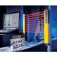
F39-EU1E Omron, F39-EU1E Datasheet - Page 97

F39-EU1E
Manufacturer Part Number
F39-EU1E
Description
F3S-B OPTIONAL PROGRAMMING KIT
Manufacturer
Omron
Datasheet
1.F39-EU1E.pdf
(865 pages)
Specifications of F39-EU1E
Leaded Process Compatible
No
Peak Reflow Compatible (260 C)
No
Light Curtain Type
Safety
Lead Free Status / RoHS Status
Contains lead / RoHS non-compliant
Lead Free Status / RoHS Status
Contains lead / RoHS non-compliant
- Current page: 97 of 865
- Download datasheet (35Mb)
Courtesy of Steven Engineering, Inc.-230 Ryan Way, South San Francisco, CA 94080-6370-Main Office: (650) 588-9200-Outside Local Area: (800) 258-9200-www.stevenengineering.com
Safety Precautions
Refer to the “Precautions for All Relays” and “Precautions for All Relays with Forcibly Guided Contacts”.
Installation
Wiring
Connector Cover
Mounting Expansion Units
Mounting Multiple Units
Applicable Safety Category (EN954-1)
G9SA-series Relays meet the requirements of Safety Category 4 of
the EN954-1 standards when they are used as shown in the examples
provided by OMRON. The Relays may not meet the standards in
some operating conditions. The OFF-delay output of models
G9SA-321-T@ and EX031-T@, however, conform to Safety
Category 3.
The applicable safety category is determined from the whole safety
control system. Make sure that the whole safety control system meets
EN954-1 requirements.
Turn OFF the G9SA before wiring the G9SA. Do not
touch the terminals of the G9SA while the power is
turned ON, because the terminals are charged and may
cause an electric shock.
The G9SA can be installed in any direction.
Use the following to wire the G9SA.
Tighten each screw to a torque of 0.78 to 1.18 N·m, or the G9SA
may malfunction or generate heat.
External inputs connected to T11 and T12 or T21 and T22 must be
no-voltage contact inputs.
PE is a ground terminal.
When a machine is grounded at the positive, the PE terminal
should not be grounded.
Do not remove the connector cover of the G9SA-301, G9SA-501,
G9SA-321-T@, or G9SA-TH301 unless an Expansion Unit is being
used.
Turn OFF the G9SA before connecting the Expansion Unit.
When an Expansion Unit is being used, remove the connector
cover from the G9SA Safety Relay Unit (G9SA-301, G9SA-501,
G9SA-321-T@, or G9SA-TH301) and insert the connector of the
Expansion Unit’s connector cable.
When mounting multiple Units close to each other, the rated
current will be 3 A. Do not apply a current higher than 3 A.
Stranded wire: 0.75 to 1.5 mm
Solid wire:
Precautions for Correct Use
1.0 to 1.5 mm
http://www.ia.omron.com/
!CAUTION
2
2
Connecting Inputs
Ground Shorts
Resetting Inputs
Resetting Inputs During OFF Delay Time
The G9SA-321-T@ operates as follows according to the reset mode
when the inputs are to be re-entered during the OFF delay time of the
G9SA-321-T@:
For auto reset, after the OFF delay time has ended, the outputs will
turn OFF, and then the outputs will turn ON again.
For manual reset, after the OFF delay time has ended, the outputs will
turn OFF, and then the outputs will turn ON again when the reset is
input.
Durability of Contact Outputs
Relay with Forcibly Guided Contact durability depends greatly on the
switching condition. Confirm the actual conditions of operation in
which the Relay will be used in order to make sure the permissible
number of switching operations.
When the accumulated number of operation exceeds its permissible
range, it can cause failure of reset of safety control circuit. In such
case, please replace the Relay immediately. If the Relay is used
continuously without replacing, then it can lead to loss of safety
function.
Certified Standards
The G9SA-301/501/321-T@/TH301/EX301/EX031-T@ conform to the
following standards.
If using multiple G9SA models, inputs cannot be made using the
same switch. This is also true for other input terminals.
A positive thermistor (TH) is built into the G9SA internal circuit to
detect ground shorts and shorts between channels 1 and 2. When
such faults are detected, the safety outputs are interrupted. If the
short breakdown is repaired, the G9SA automatically recovers.
When only channel 1 of the 2-channel input turns OFF, the safety
output is interrupted. In order to restart when this happens, it is
necessary to turn OFF and ON both input channels. It is not
possible to restart by resetting only channel 1.
EN standards, certified by BG:
EN954-1
EN60204-1
EN574 (G9SA-TH301 only)
Conformance to EMC (Electromagnetic Compatibility)
Certified by TÜV Product Service: G9SA (-TH301) 24 VAC/VDC
Certified by TÜV Rheinland:
EMI (Emission):
EMS (Immunity):
UL standards: UL508 (Industrial Control Equipment)
CSA standards: CSA C22.2 No. 14 (Industrial Control Equipment)
(c)Copyright OMRON Corporation 2007 All Rights Reserved.
Incorrect
T11 T12
G9SA
T11 T12
G9SA-EX301/EX031-T@
G9SA (-TH301) 100-240 VAC
EN55011 Group 1 Class A
EN61000-6-2
G9SA
G9SA
13
Related parts for F39-EU1E
Image
Part Number
Description
Manufacturer
Datasheet
Request
R

Part Number:
Description:
Pair Of Flat Mounting Brackets (transmitter & Receiver)
Manufacturer:
Omron

Part Number:
Description:
Pair Of Protective Shrouds (transmitter & Receiver)
Manufacturer:
Omron

Part Number:
Description:
G6S-2GLow Signal Relay
Manufacturer:
Omron Corporation
Datasheet:

Part Number:
Description:
Compact, Low-cost, SSR Switching 5 to 20 A
Manufacturer:
Omron Corporation
Datasheet:

Part Number:
Description:
Manufacturer:
Omron Corporation
Datasheet:


