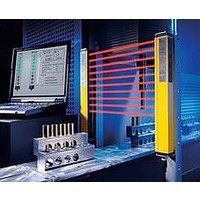
F39-EU1E Omron, F39-EU1E Datasheet - Page 761

F39-EU1E
Manufacturer Part Number
F39-EU1E
Description
F3S-B OPTIONAL PROGRAMMING KIT
Manufacturer
Omron
Datasheet
1.F39-EU1E.pdf
(865 pages)
Specifications of F39-EU1E
Leaded Process Compatible
No
Peak Reflow Compatible (260 C)
No
Light Curtain Type
Safety
Lead Free Status / RoHS Status
Contains lead / RoHS non-compliant
Lead Free Status / RoHS Status
Contains lead / RoHS non-compliant
- Current page: 761 of 865
- Download datasheet (35Mb)
Courtesy of Steven Engineering, Inc.-230 Ryan Way, South San Francisco, CA 94080-6370-Main Office: (650) 588-9200-Outside Local Area: (800) 258-9200-www.stevenengineering.com
Accessories
Control Units
* For further details on the G9SA-300-SC, refer to G9SA-300-SC.
Setting Console
Spatter Protection Slit Covers
* The maximum distance that can turn ON all of the five light intensity level indicators.
Environment-resistant Enclosures
* To conform to IP67, tighten the screws according to the “Cautions for Use” as described in the manual packaged together with the product.
For details on the setting console, refer to the
instruction manual provided with the product.
Item
Applicable sensor
Supply voltage
Power consumption
Operating time
Response time
Relay output
Connection
method
Weight (packed state)
Accessory
Item
Applicable sensor
Supply voltage
Connection method
Weight (packed state)
Accessories
Item
Applicable sensor
Operating range
(typical value) *
Distance that does
not cause mutual
interference
(typical value)
Item
Applicable sensor
Operating range characteristics
Degree of protection *
Materials
Model
No. of contact
Rated load
Rated carry voltage
Between sensor’s
Other
When one cover is
used
When two covers are
used
When one cover is
used
When two covers are
used
http://www.ia.omron.com/
F3SN-A, F3SH-A
24 VDC ±10% (provided from the sensor)
Cable (included)
360 g
One branching connector, 2-m cable,
one connector cap, instruction manual
Model
Model
Model
F3SN-A, F3SN-B, F3SH-A
24 VDC ±10%
1.7 W DC max. (does not include the sensor’s
current consumption)
100 ms max. (does not include the sensor’s
response time)
10 ms max. (does not include the sensor’s
response time)
3 NO + 1 NC
25 VAC, 5 A (cos diameter = 1), 30 VDC, 5 A L/R = 0 ms
5 A
M12 connector (8 pins)
Terminal block
Approx. 280 g
Instruction manual
F39-MC11
F3SN-A@@@@P14(-01)
0.2 to 6 m
IP67 (IEC60529)
Case: Acrylic resin, rubber: NBR60, mounting bracket: SUS316L, screw: SUS316L
F3SN-A@@@@P14(-01)
3 m
1 m
6.5 m
2.4 m
F39-HS@@@@A-14
F39-HP@@@@-14
F3SP-B1P
2 m
0.5 m
4.8 m
1.2 m
F39-HS@@@@B-14
External Indicators
* The indicator must be secured separately for models ending in “-04”
Item
Applicable sensor
Light source
Supply voltage
Current consumption
Connection method
Weight (packed state)
or “-05.” For the F3SN-B, only light-ON mode can be used.
(c)Copyright OMRON Corporation 2007 All Rights Reserved.
24 VDC: 0.7 W DC max. (does not include the
sensor’s current consumption)
300 ms max. (does not include the sensor’s
response time and bounce time)
10 ms max. (does not include the sensor’s
response time and bounce time)
3 NO
Approx. 300 g
250 VAC, 5 A
F3SN-A@@@@P@@(-01), F3SN-B@@@@P@@(-01),
F3SH-A09P03(-01)
0.2 to 10 m
Model
F3SN-A@@@@P@@(-01), F3SN-B@@@@P@@(-01),
F3SH-A09P03(-01)
5.5 m
2 m
12.2 m
4.4 m
F39-HS@@@@A-25
F39-HSH09A-03
F3SN-A/F3SN-B/F3SH-A
F3SN-A@@@@P@@-01(-03, -04, -05) *
F3SH-A09P03-01
Red LED
24 VDC ±10% (provided from the sensor)
50 mA max. (provided from the sensor)
M12 connector (8 pins)
Approx. 80 g
F39-A01PR-L
F39-A01PR-D
(Receiver)
(Emitter)
F39-HP@@@@-25
G9SA-300-SC *
F39-HPH09-03
3.5 m
1 m
7.8 m
2.1 m
F39-HS@@@@B-25
Green LED
F39-HSH09B-03
F39-A01PG-D
F39-A01PG-L
(Receiver)
(Emitter)
12
Related parts for F39-EU1E
Image
Part Number
Description
Manufacturer
Datasheet
Request
R

Part Number:
Description:
Pair Of Flat Mounting Brackets (transmitter & Receiver)
Manufacturer:
Omron

Part Number:
Description:
Pair Of Protective Shrouds (transmitter & Receiver)
Manufacturer:
Omron

Part Number:
Description:
G6S-2GLow Signal Relay
Manufacturer:
Omron Corporation
Datasheet:

Part Number:
Description:
Compact, Low-cost, SSR Switching 5 to 20 A
Manufacturer:
Omron Corporation
Datasheet:

Part Number:
Description:
Manufacturer:
Omron Corporation
Datasheet:


