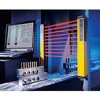
F39-EU1E Omron, F39-EU1E Datasheet - Page 471

F39-EU1E
Manufacturer Part Number
F39-EU1E
Description
F3S-B OPTIONAL PROGRAMMING KIT
Manufacturer
Omron
Datasheet
1.F39-EU1E.pdf
(865 pages)
Specifications of F39-EU1E
Leaded Process Compatible
No
Peak Reflow Compatible (260 C)
No
Light Curtain Type
Safety
Lead Free Status / RoHS Status
Contains lead / RoHS non-compliant
Lead Free Status / RoHS Status
Contains lead / RoHS non-compliant
- Current page: 471 of 865
- Download datasheet (35Mb)
Courtesy of Steven Engineering, Inc.-230 Ryan Way, South San Francisco, CA 94080-6370-Main Office: (650) 588-9200-Outside Local Area: (800) 258-9200-www.stevenengineering.com
Connection Example with OMRON’s G9SA Safety Relay Unit
G9SA-321-T@ (24 VAC/VDC) + D4BL-@D@A-@, -@D@B-@ (Mechanical Lock Type) Circuit Diagram
(Manual Reset)
Lock release signal
Guard
Stop signal
S4
OPEN
KM1
KM2
http://www.ia.omron.com/
Timing Chart
Motor rotation
Guard Lock
Safety-door
Switch S2
Lock release
signal
S4
Limit switch S1
Stop signal
Reset switch
S3
K1 and K2
(NC)
K1 and K2
(NO)
K3 and K4
(NC)
K3 and K4
(NO)
KM1 and KM2
(NC)
KM1 and KM2
(NO)
Operation
instruction
31
32
11
12
21
22
A1 A2 T11
TH
SA
S1
PLC
PE T21
S2
a
K1
T12
K1
6
OFF-delay time
b
K2
T23 T22
K2
K3
K4
Off-Delay
Timer
1
Guard opens
S3
a
b
T31
Control
Circuit
A
B
K3
K4
T32
Feedback loop
KM1
KM2
Guard can be opened
2
5
K1
K2
S1:
S2:
S3:
S4:
KM1 and KM2: Magnetic Contactor
M:
3
4
Note: This example circuit is for Category 3.
13 23 33 43 53 61
14 24 34
(c)Copyright OMRON Corporation 2007 All Rights Reserved.
KM1 KM2
44 54 62
Operation
instruction
Safety Limit Switch
Guard Lock Safety-door Switch
Reset switch
Lock release switch
3-phase motor
with direct opening mechanism
(D4B-N, D4N, D4F)
KM1
KM2
JP
Motor controller
1
2
3
4
5
6
M
D4BL
11
Related parts for F39-EU1E
Image
Part Number
Description
Manufacturer
Datasheet
Request
R

Part Number:
Description:
Pair Of Flat Mounting Brackets (transmitter & Receiver)
Manufacturer:
Omron

Part Number:
Description:
Pair Of Protective Shrouds (transmitter & Receiver)
Manufacturer:
Omron

Part Number:
Description:
G6S-2GLow Signal Relay
Manufacturer:
Omron Corporation
Datasheet:

Part Number:
Description:
Compact, Low-cost, SSR Switching 5 to 20 A
Manufacturer:
Omron Corporation
Datasheet:

Part Number:
Description:
Manufacturer:
Omron Corporation
Datasheet:


