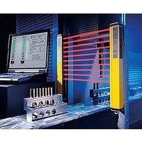
F39-EU1E Omron, F39-EU1E Datasheet - Page 762

F39-EU1E
Manufacturer Part Number
F39-EU1E
Description
F3S-B OPTIONAL PROGRAMMING KIT
Manufacturer
Omron
Datasheet
1.F39-EU1E.pdf
(865 pages)
Specifications of F39-EU1E
Leaded Process Compatible
No
Peak Reflow Compatible (260 C)
No
Light Curtain Type
Safety
Lead Free Status / RoHS Status
Contains lead / RoHS non-compliant
Lead Free Status / RoHS Status
Contains lead / RoHS non-compliant
- Current page: 762 of 865
- Download datasheet (35Mb)
Courtesy of Steven Engineering, Inc.-230 Ryan Way, South San Francisco, CA 94080-6370-Main Office: (650) 588-9200-Outside Local Area: (800) 258-9200-www.stevenengineering.com
Connections
Wiring for Sensor Only Configuration
Wiring for the Manual Reset Mode and the EDM Function
Series Connection (Up to 3 Sets)
Using series connection models (model numbers ending in -01, -03,
-04, -05) enables series connection as shown in the figure at the right.
Either stand-alone models and the series connection models can be
used for the light curtains located at the top end.
Note: 1. To maintain performance characteristics, use the F39-
Emitter cable
F39-JC@A-L
2. The F3SN and F3SH cannot be connected in series.
3. Series connection is possible for model numbers ending in
(See
note 1.)
S1
JCR2B or the F39-JC3B to connect light curtains in series.
The F39-JC7B, F39-JC10B, or F39-JC15B cannot be
connected in series.
-04 or -05 (with 0.2 m cable with connectors).
Refer to page 2.
(See
note 1.)
S2
Emitter
http://www.ia.omron.com/
RS-485(A) (Gray)
RS-485(B) (Pink)
Receiver
K1
K2
K3
Receiver cable
F39-JC@A-D
K1
K2
+24 VDC
0 V
Power
supply
Wiring for the Auto-reset Mode
When the EDM is Not Used
When the EDM is not necessary
(1) Use the F39-MC11 to disable the EDM.
or
(2) Disable the EDM by changing the wiring as shown in the
Note: 1. Use very low load type switches.
S1:
S2:
S3:
K1, K2: Relay that control the dangerous zone, etc.
K3:
figure below, when the auxiliary output is Dark ON.
(c)Copyright OMRON Corporation 2007 All Rights Reserved.
Emitter
Emitter
Cable with Connectors
on Both Ends (for Emitter)
F39-JCR2B-L,
F39-JCR5B-L,
or
F39-JC3B-L
Cable with Connector
on One End
(for Emitter)
F39-JC@A-L
2. If K3 is not necessary, short-circuit the auxiliary
(See notes 1 and 3.)
External test switch
Interlock/lockout reset switch
Lockout reset switch (If the switch is not necessary,
connect between the reset input and +24 VDC.)
Load, PLC, etc. (used for monitoring)
(See
note 1.)
output with the EDM input.
S1
Emitter
(See
note 1.)
S3
F3SN-A/F3SN-B/F3SH-A
Receiver
F3SN-A@@@@P@@(-@@)*
Receiver
F3SN-A@@@@P@@-01
(or -03, -04, -05) *
Cable with Connectors
on Both Ends (for Receiver)
F39-JCR2B-D,
F39-JCR5B-D,
or
F39-JC3B-D
(See notes 1 and 3.)
Cable with Connector
on One End
(for Receiver)
F39-JC@A-D
(See note 2.)
Receiver
K3
K1
* Series connection is
possible for the F3SN-B.
13
Related parts for F39-EU1E
Image
Part Number
Description
Manufacturer
Datasheet
Request
R

Part Number:
Description:
Pair Of Flat Mounting Brackets (transmitter & Receiver)
Manufacturer:
Omron

Part Number:
Description:
Pair Of Protective Shrouds (transmitter & Receiver)
Manufacturer:
Omron

Part Number:
Description:
G6S-2GLow Signal Relay
Manufacturer:
Omron Corporation
Datasheet:

Part Number:
Description:
Compact, Low-cost, SSR Switching 5 to 20 A
Manufacturer:
Omron Corporation
Datasheet:

Part Number:
Description:
Manufacturer:
Omron Corporation
Datasheet:


