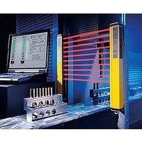
F39-EU1E Omron, F39-EU1E Datasheet - Page 328

F39-EU1E
Manufacturer Part Number
F39-EU1E
Description
F3S-B OPTIONAL PROGRAMMING KIT
Manufacturer
Omron
Datasheet
1.F39-EU1E.pdf
(865 pages)
Specifications of F39-EU1E
Leaded Process Compatible
No
Peak Reflow Compatible (260 C)
No
Light Curtain Type
Safety
Lead Free Status / RoHS Status
Contains lead / RoHS non-compliant
Lead Free Status / RoHS Status
Contains lead / RoHS non-compliant
- Current page: 328 of 865
- Download datasheet (35Mb)
Courtesy of Steven Engineering, Inc.-230 Ryan Way, South San Francisco, CA 94080-6370-Main Office: (650) 588-9200-Outside Local Area: (800) 258-9200-www.stevenengineering.com
1. Make the rear edge of the object smooth with an angle of 15 to 30
2. Design the circuit so that no error signal will be generated.
3. Use or set a switch that is actuated in one direction only.
Unbalanced force must not be imposed on the actuator. Otherwise,
wear and tear on the actuator may result.
Make sure that the actuator does not exceed the OT (overtravel)
range, otherwise the Limit Switch may malfunction. When
mounting the Limit Switch, be sure to adjust the Limit Switch
carefully while considering the whole movement of the actuator.
The Limit Switch may soon malfunction if the OT is excessive.
Therefore, adjustments and careful consideration of the position of
the Limit Switch and the expected OT of the actuator are
necessary when mounting the Limit Switch.
Be sure to use the Limit Switch according to the characteristics of
the actuator.
If a roller arm lever actuator is used, do not attempt to actuate the
Limit Switch in the direction shown below.
Do not modify the actuator to change the OP.
In the case of a long actuator of an adjustable roller lever type, the
following countermeasures against lever shaking are
recommended.
or make it in the shape of a quadratic curve.
(Also, set the switch for operation in one direction only.)
Dog
Incorrect
Roller
Correct
Dog
Incorrect
Optimum setting
range
http://www.ia.omron.com/
Install a stopper.
80% of
rated OT
100% of
rated OT
Distance to the optimum
setting range.
PT (Pretravel)
Stopper
Dog
Correct
Roller
OT (Overtravel)
FP (Free position)
OP (Operating position)
TTP (Total travel position)
Reference line
Operating Environment
Switch Contacts
Switch contacts can be used with both standard loads and
microloads, but once a contact has been used to switch a standard
load, it cannot be used for a load of a smaller capacity.
Doing so may result in roughening of the contact surface and contact
reliability may be lost.
Storing Switches
Do not store the Switch in locations where toxic gases, such as H
SO
subject to, excessive dirt, excessive dust, high temperature, or high
humidity.
Other Precautions
Dog Design
Operating Speed, Dog Angle, and Relationship with
Actuator
Before designing a dog, carefully consider the operating speed and
angle of the dog and their relationship with the shape of the actuator.
The optimum operating speed (V) of a standard dog at an angle of 30
to 45 is 0.5 m/s maximum.
Roller Lever Models
1. Non-overtravel Dog
30
45
60
60 to 90
These Switches are for indoor applications.
The Switches may fail if they are used outdoors.
Do not use the Switch in locations where toxic gases, such as H
SO
subject to high temperatures or humidity. Doing so may damage
the Switch due to contact failure or corrosion.
Do not use the Switches in the following locations.
·
·
·
·
·
·
When attaching a cover, be sure that the seal rubber is in place and
that there is no foreign material present. If the cover is attached
with the seal rubber out of place or if foreign material is stuck to the
rubber, a proper seal will not be obtained.
Perform maintenance inspections periodically.
Use the Switch with a load current that does not exceed the rated
current.
Do not use any screws to connect the cover other than the
specified ones. The seal characteristics may be reduced.
2
Locations subject to severe temperature changes
Locations subject to high temperatures or condensation
Locations subject to severe vibration
Locations where the interior of the Protective Door may come into
direct contact with cutting chips, metal filings, oil, or chemicals
Locations where the Switch may come into contact with thinner or
detergents
Locations where explosive or flammable gases are present
, NH
Dog speed: 0.5 m/s max. (Standard Speed)
2
(c)Copyright OMRON Corporation 2007 All Rights Reserved.
, NH
3
, HNO
3
, HNO
3
, and Cl
Precautions for All Safety Limit Switches
3
, and Cl
0.4
0.25
0.1
0.05 (low speed)
Lever set vertically
2
, may be present, or in locations that are
V max. (m/s)
2
, may be present, or in locations that are
φ
0.8 (TT)
80% of totaltravel
y
2
2
S,
S,
C-2
Related parts for F39-EU1E
Image
Part Number
Description
Manufacturer
Datasheet
Request
R

Part Number:
Description:
Pair Of Flat Mounting Brackets (transmitter & Receiver)
Manufacturer:
Omron

Part Number:
Description:
Pair Of Protective Shrouds (transmitter & Receiver)
Manufacturer:
Omron

Part Number:
Description:
G6S-2GLow Signal Relay
Manufacturer:
Omron Corporation
Datasheet:

Part Number:
Description:
Compact, Low-cost, SSR Switching 5 to 20 A
Manufacturer:
Omron Corporation
Datasheet:

Part Number:
Description:
Manufacturer:
Omron Corporation
Datasheet:


