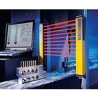
F39-EU1E Omron, F39-EU1E Datasheet - Page 813

F39-EU1E
Manufacturer Part Number
F39-EU1E
Description
F3S-B OPTIONAL PROGRAMMING KIT
Manufacturer
Omron
Datasheet
1.F39-EU1E.pdf
(865 pages)
Specifications of F39-EU1E
Leaded Process Compatible
No
Peak Reflow Compatible (260 C)
No
Light Curtain Type
Safety
Lead Free Status / RoHS Status
Contains lead / RoHS non-compliant
Lead Free Status / RoHS Status
Contains lead / RoHS non-compliant
- Current page: 813 of 865
- Download datasheet (35Mb)
Courtesy of Steven Engineering, Inc.-230 Ryan Way, South San Francisco, CA 94080-6370-Main Office: (650) 588-9200-Outside Local Area: (800) 258-9200-www.stevenengineering.com
Distance from Glossy Surface
Others
To use the Safety Light Curtain in PSDI mode (restart of
cycle operation by the sensor), you must configure an
appropriate circuit between the Safety Light Curtain and
the machine. For details about PSDI, refer to
OSHA1910.217, IEC61496-1, and other relevant
standards and regulations.
Do not try to disassemble, repair, or modify this product.
Doing so may cause the safety functions to stop working
properly.
Do not use the Safety Light Curtain in environments
where flammable or explosive gases are present. Doing
so may result in explosion.
Perform daily and 6-month inspections for the Safety
Light Curtain. Otherwise, the system may fail to work
properly, resulting in serious injury.
Install the sensor system so that it is not affected by
reflection from a glossy surface. Failure to do so may
hinder detection, resulting in serious injury.
Install the sensor system at distance D or further from
highly reflective surfaces such as metallic walls, floors,
ceilings, or workpieces, as shown below.
For 0.2 to 3 m
For 3 m or more
<Side View>
(Detection Distance)
emitter and receiver
Emitter
Distance between
Reflective ceiling
Detection zone
Reflective floor
L
D
D
http://www.ia.omron.com/
Receiver
0.13 m
L/2 x tan5
= L x 0.044 (m)
Allowable installation distance D
Type 4
Emitter
<Top View>
=5° (F3SN-A, F3SN-A@SS,
=10° (F3SN-B)
Reflective surface
F3SH-A, F3SJ)
0.26 m
L/2 x tan10
= L x 0.088 (m)
L
D
Type 2
Receiver
Installation
Prevention of Mutual Interference
The emitter and the receiver to be set facing each other
should be a pair of the same set. Erroneous combination
may create a zone where objects cannot be detected.
Do not use a sensor system in a reflective configuration.
Doing so may hinder detection.
Mirrors can be used change the optical route.
When using more than 1 set of Safety Light Curtain,
install them so that mutual interference does not occur,
such as by configuring series connections or using
physical barriers between adjacent sets.
(c)Copyright OMRON Corporation 2007 All Rights Reserved.
Precautions for All Safety Sensors
C-3
Related parts for F39-EU1E
Image
Part Number
Description
Manufacturer
Datasheet
Request
R

Part Number:
Description:
Pair Of Flat Mounting Brackets (transmitter & Receiver)
Manufacturer:
Omron

Part Number:
Description:
Pair Of Protective Shrouds (transmitter & Receiver)
Manufacturer:
Omron

Part Number:
Description:
G6S-2GLow Signal Relay
Manufacturer:
Omron Corporation
Datasheet:

Part Number:
Description:
Compact, Low-cost, SSR Switching 5 to 20 A
Manufacturer:
Omron Corporation
Datasheet:

Part Number:
Description:
Manufacturer:
Omron Corporation
Datasheet:


