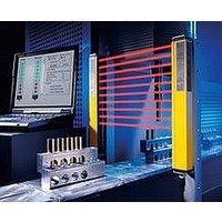
F39-EU1E Omron, F39-EU1E Datasheet - Page 682

F39-EU1E
Manufacturer Part Number
F39-EU1E
Description
F3S-B OPTIONAL PROGRAMMING KIT
Manufacturer
Omron
Datasheet
1.F39-EU1E.pdf
(865 pages)
Specifications of F39-EU1E
Leaded Process Compatible
No
Peak Reflow Compatible (260 C)
No
Light Curtain Type
Safety
Lead Free Status / RoHS Status
Contains lead / RoHS non-compliant
Lead Free Status / RoHS Status
Contains lead / RoHS non-compliant
- Current page: 682 of 865
- Download datasheet (35Mb)
Courtesy of Steven Engineering, Inc.-230 Ryan Way, South San Francisco, CA 94080-6370-Main Office: (650) 588-9200-Outside Local Area: (800) 258-9200-www.stevenengineering.com
NPN Output Type
The numbers in white circles indicate the connector's pin numbers.
The black circles indicate connectors for series connection.
The words in brackets ([ ]) indicate the signal name for muting system.
Single-end Connector Cable
*1. Basic system indicates a system with default factory settings.
*2. N.C. for models with the "-TS" suffix.
F39-
JC3A (3 m)
F39-
JC7A (7 m)
F39-
JC10A (10 m)
F39-
JC15A (15 m)
Muting system indicates a system attached with a muting keycap (F39-CN6) to enable muting function.
Model
External indicator output 2
External indicator output 1
3
4
2
5
8
http://www.ia.omron.com/
6
1
7
Brown
1
2
3
4
5
6
7
8
Brown
Blue
Blue
Internal wiring
Communication line (+)
10
10
5
5
Gray
Gray
Wire color
Main Circuit 2
Main Circuit 1
Indication
5
5
Main Circuit
Receiver
Receiver
Indication
White
Brown
Green
Yellow
Gray
Pink
Blue
Red
Emitter
6
6
Pink
Pink
Communication line (−)
(1) White Safety output 2
(2) Brown +24 VDC
(3) Green Control output 1 Test Input
(4) Yellow Auxiliary output 1 Reset input
(5) Gray
(6) Pink
(7) Blue
(8) Red
Pin
No.
color
Wire
Communication
line (+)
Communication
line (-)
0 V
External device
monitoring input
Receiver
Basic system *1
(c)Copyright OMRON Corporation 2008 All Rights Reserved.
1
4
1
3
8
7
2
3
8
7
2
1
4
Green
Yellow
Brown
Green Test input
White Interlock selection input
Blue
Yellow
Red
Brown
White
Red
Blue
Interlock
selection input *2
+24 VDC
Communication
line (+)
Communication
line (-)
0 V
Auxiliary output 2
*2
Shield
Control output 2
Control output 1
Auxiliary output 1
Shield
Emitter
[Muting input 1]
Auxiliary output 2
[Muting input 2]
Reset input
External device
monitoring input
Signal Name
Load
Safety output 2
+24 VDC
Control output 1 Test Input
Auxiliary output 1 Reset input
Communication
line (+)
Communication
line (-)
0 V
External device
monitoring input
Load
Receiver
Muting system *1
+24 VDC
F3SJ Ver.2
Load
Muting input 1
+24 VDC
Communication
line (+)
Communication
line (-)
0 V
Muting input 2
Emitter
0 V
28
Related parts for F39-EU1E
Image
Part Number
Description
Manufacturer
Datasheet
Request
R

Part Number:
Description:
Pair Of Flat Mounting Brackets (transmitter & Receiver)
Manufacturer:
Omron

Part Number:
Description:
Pair Of Protective Shrouds (transmitter & Receiver)
Manufacturer:
Omron

Part Number:
Description:
G6S-2GLow Signal Relay
Manufacturer:
Omron Corporation
Datasheet:

Part Number:
Description:
Compact, Low-cost, SSR Switching 5 to 20 A
Manufacturer:
Omron Corporation
Datasheet:

Part Number:
Description:
Manufacturer:
Omron Corporation
Datasheet:


