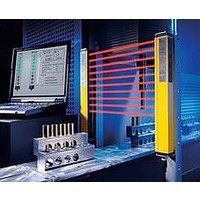
F39-EU1E Omron, F39-EU1E Datasheet - Page 362

F39-EU1E
Manufacturer Part Number
F39-EU1E
Description
F3S-B OPTIONAL PROGRAMMING KIT
Manufacturer
Omron
Datasheet
1.F39-EU1E.pdf
(865 pages)
Specifications of F39-EU1E
Leaded Process Compatible
No
Peak Reflow Compatible (260 C)
No
Light Curtain Type
Safety
Lead Free Status / RoHS Status
Contains lead / RoHS non-compliant
Lead Free Status / RoHS Status
Contains lead / RoHS non-compliant
- Current page: 362 of 865
- Download datasheet (35Mb)
Courtesy of Steven Engineering, Inc.-230 Ryan Way, South San Francisco, CA 94080-6370-Main Office: (650) 588-9200-Outside Local Area: (800) 258-9200-www.stevenengineering.com
Precautions for All Safety Limit Switches
Note: Refer to the “Safety Precautions” section for each Switch for specific precautions applicable to each Switch.
Mechanical Characteristics
Operating Force, Stroke, and Contact Characteristics
Do not use the Switch in atmospheres containing explosive or
flammable gases.
Although the switch box is protected from dust or water
penetration, the head is not protected from minute foreign matter
or water penetration. Ensure that minute foreign matter and water
do not penetrate the head. Failure to do so may result in
accelerated wear, Switch damage, or malfunctioning.
The durability of the Switch varies considerably depending on the
switching conditions. Always confirm the usage conditions by using
the Switch in an actual application, and use the Switch only for the
number of switching operations that its performance allows.
Do not use the Switch as a stopper.
Do not use the Switch in a startup circuit. Use it instead for a safety
confirmation signal.
Check the Switches before use and inspect regularly, replacing
them when necessary. If a Switch is kept pressed for an extended
period of time, the components may deteriorate quickly, and the
Switch may not release.
To protect the Switch from damage due to short-circuits, be sure to
connect a quick-response fuse with a breaking current 1.5 to 2
times larger than the rated current in series with the Switch.
When complying with EN certified ratings, use a 10 A IEC 60269-
compliant gI or gG fuse.
Do not drop the Switch. Doing so may prevent it from functioning
to its full capacity.
Do not disassemble or modify the Switch. Doing so may prevent it
from operating correctly.
The following graph indicates the relationship between operating
force and stroke or stroke and contact force. In order to operate the
Limit Switch with high reliability, it is necessary to use the Limit
Switch within an appropriate contact force range. If the Limit Switch
is used in the normally closed condition, the dog must be installed
so that the actuator will return to the FP when the actuator is
actuated by the object. If the Limit Switch is used in the normally
open condition, the actuator must be pressed to 80% to 100% of
the OT (i.e., 60% to 80% of the TT) and any slight fluctuation must
be absorbed by the actuator.
If the full stroke is set close to the OP or RP, contact instability may
result. If the full stroke is set to the TTP, the actuator or switch may
become damaged due to the inertia of the dog. In that case, adjust
the stroke with the mounting panel or the dog. Refer to page C-2,
Dog Design, page C-3, Stroke Settings vs. Dog Movement
Distance, and page C-3, Dog Surface for details.
The following graph shows an example of changes in contact force
according to the stroke. The contact force near the OP or RP is
unstable, and the Limit Switch cannot maintain high reliability.
Furthermore, the Limit Switch cannot withstand strong vibration or
shock.
Precautions for Correct Use
Precautions for Safe Use
http://www.ia.omron.com/
Operation
If the Limit Switch is used so that the actuator is constantly
pressed, it will fail quickly and reset faults may occur. Inspect the
Limit Switch periodically and replace it as required.
Carefully determine the proper cam or dog so that the actuator will
not abruptly snap back, thus causing shock. In order to operate the
Limit Switch at a comparatively high speed, use a cam or dog with
a long enough stroke that keeps the Limit Switch turned ON for a
sufficient time so that the relay or valve will be sufficiently
energized.
The operating method, the shape of the dog or cam, the operating
frequency, and the travel after operation have a large influence on
the durability and operating accuracy of the Limit Switch. The cam
must be smooth in shape.
Appropriate force must be imposed on the actuator by the cam or
another object in both rotary operation and linear operation.
If the object touches the lever as shown below, the operating
position will not be stable.
Snapped
back
Snapped
back
(c)Copyright OMRON Corporation 2007 All Rights Reserved.
Incorrect
Abruptly
actuated
Dog
Abruptly
actuated
Operating force
Changes to opposite side
Changes to opposite side
Contact force
Incorrect
Incorrect
OTP
FP
Correct
Dog
Correct
Correct
Stroke
Stroke
C-1
Related parts for F39-EU1E
Image
Part Number
Description
Manufacturer
Datasheet
Request
R

Part Number:
Description:
Pair Of Flat Mounting Brackets (transmitter & Receiver)
Manufacturer:
Omron

Part Number:
Description:
Pair Of Protective Shrouds (transmitter & Receiver)
Manufacturer:
Omron

Part Number:
Description:
G6S-2GLow Signal Relay
Manufacturer:
Omron Corporation
Datasheet:

Part Number:
Description:
Compact, Low-cost, SSR Switching 5 to 20 A
Manufacturer:
Omron Corporation
Datasheet:

Part Number:
Description:
Manufacturer:
Omron Corporation
Datasheet:


