ATEVK1104 Atmel, ATEVK1104 Datasheet - Page 263
ATEVK1104
Manufacturer Part Number
ATEVK1104
Description
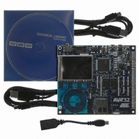
KIT DEV/EVAL FOR AVR32 AT32UC3A
Manufacturer
Atmel
Series
AVR®32r
Type
MCUr
Datasheets
1.ATAVRONE-PROBECBL.pdf
(16 pages)
2.ATEVK1104.pdf
(826 pages)
3.ATEVK1104.pdf
(90 pages)
4.ATEVK1104.pdf
(6 pages)
5.ATEVK1104.pdf
(12 pages)
Specifications of ATEVK1104
Contents
Evaluation Board, Software and Documentation
Processor To Be Evaluated
AT32UC3A3
Data Bus Width
32 bit
Interface Type
USB, SPI, USART
Silicon Manufacturer
Atmel
Core Architecture
AVR
Core Sub-architecture
AVR UC3
Silicon Core Number
AT32UC3A3256
Silicon Family Name
AVR
Kit Contents
Board CD Docs
Rohs Compliant
Yes
For Use With/related Products
AT32UC3A3
Lead Free Status / RoHS Status
Lead free / RoHS Compliant
Available stocks
Company
Part Number
Manufacturer
Quantity
Price
Company:

Part Number:
ATEVK1104
Manufacturer:
Atmel
Quantity:
135


25.7.1.1
25.7.1.2
32058J-AVR32-04/11
Clock Divider
Transmitter Clock Management
Figure 25-4. Divided Clock Block Diagram
The Master Clock divider is determined by the 12-bit field DIV counter and comparator (so its
maximal value is 4095) in the Clock Mode Register CMR, allowing a Master Clock division by up
to 8190. The Divided Clock is provided to both the Receiver and Transmitter. When this field is
programmed to 0, the Clock Divider is not used and remains inactive.
When DIV is set to a value equal to or greater than 1, the Divided Clock has a frequency of Mas-
ter Clock divided by 2 times DIV. Each level of the Divided Clock has a duration of the Master
Clock multiplied by DIV. This ensures a 50% duty cycle for the Divided Clock regardless of
whether the DIV value is even or odd.
Figure 25-5.
Table 25-2.
The transmitter clock is generated from the receiver clock or the divider clock or an external
clock scanned on the TX_CLOCK I/O pad. The transmitter clock is selected by the CKS field in
TCMR (Transmit Clock Mode Register). Transmit Clock can be inverted independently by the
CKI bits in TCMR.
Maximum
CLK_SSC / 2
Divided Clock
Master Clock
Master Clock
Divided Clock
Divided Clock Generation
DIV = 3
DIV = 1
CLK_SSC
/ 2
Divided Clock Frequency = CLK_SSC/2
Divided Clock Frequency = CLK_SSC/6
Clock Divider
12-bit Counter
Minimum
CLK_SSC / 8190
CMR
Divided Clock
AT32UC3A
263
Related parts for ATEVK1104
Image
Part Number
Description
Manufacturer
Datasheet
Request
R

Part Number:
Description:
DEV KIT FOR AVR/AVR32
Manufacturer:
Atmel
Datasheet:

Part Number:
Description:
INTERVAL AND WIPE/WASH WIPER CONTROL IC WITH DELAY
Manufacturer:
ATMEL Corporation
Datasheet:
Part Number:
Description:
Low-Voltage Voice-Switched IC for Hands-Free Operation
Manufacturer:
ATMEL Corporation
Datasheet:
Part Number:
Description:
MONOLITHIC INTEGRATED FEATUREPHONE CIRCUIT
Manufacturer:
ATMEL Corporation
Datasheet:
Part Number:
Description:
AM-FM Receiver IC U4255BM-M
Manufacturer:
ATMEL Corporation
Datasheet:
Part Number:
Description:
Monolithic Integrated Feature Phone Circuit
Manufacturer:
ATMEL Corporation
Datasheet:
Part Number:
Description:
Multistandard Video-IF and Quasi Parallel Sound Processing
Manufacturer:
ATMEL Corporation
Datasheet:
Part Number:
Description:
High-performance EE PLD
Manufacturer:
ATMEL Corporation
Datasheet:
Part Number:
Description:
8-bit Flash Microcontroller
Manufacturer:
ATMEL Corporation
Datasheet:
Part Number:
Description:
2-Wire Serial EEPROM
Manufacturer:
ATMEL Corporation
Datasheet: