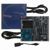
ATEVK1104 Atmel, ATEVK1104 Datasheet - Page 642

ATEVK1104
Manufacturer Part Number
ATEVK1104
Description
KIT DEV/EVAL FOR AVR32 AT32UC3A
Manufacturer
Atmel
Series
AVR®32r
Type
MCUr
Datasheets
1.ATAVRONE-PROBECBL.pdf
(16 pages)
2.ATEVK1104.pdf
(826 pages)
3.ATEVK1104.pdf
(90 pages)
4.ATEVK1104.pdf
(6 pages)
5.ATEVK1104.pdf
(12 pages)
Specifications of ATEVK1104
Contents
Evaluation Board, Software and Documentation
Processor To Be Evaluated
AT32UC3A3
Data Bus Width
32 bit
Interface Type
USB, SPI, USART
Silicon Manufacturer
Atmel
Core Architecture
AVR
Core Sub-architecture
AVR UC3
Silicon Core Number
AT32UC3A3256
Silicon Family Name
AVR
Kit Contents
Board CD Docs
Rohs Compliant
Yes
For Use With/related Products
AT32UC3A3
Lead Free Status / RoHS Status
Lead free / RoHS Compliant
Available stocks
Company
Part Number
Manufacturer
Quantity
Price
Company:
Part Number:
ATEVK1104
Manufacturer:
Atmel
Quantity:
135
- ATAVRONE-PROBECBL PDF datasheet
- ATEVK1104 PDF datasheet #2
- ATEVK1104 PDF datasheet #3
- ATEVK1104 PDF datasheet #4
- ATEVK1104 PDF datasheet #5
- Current page: 642 of 826
- Download datasheet (20Mb)
31.6.1.3
32058J–AVR32–04/11
Clock Control
Each channel can independently select an internal or external clock source for its counter:
• Internal clock signals: TIMER_CLOCK1, TIMER_CLOCK2, TIMER_CLOCK3,
• External clock signals: XC0, XC1 or XC2. The Peripherals Chapter details the connection of
This selection is made by the TCCLKS bits in the TC Channel Mode Register .
The selected clock can be inverted with the CLKI bit in CMR. This allows counting on the oppo-
site edges of the clock.
The burst function allows the clock to be validated when an external signal is high. The BURST
parameter in the Mode Register defines this signal (none, XC0, XC1, XC2).
Note:
Figure 31-2. Clock Selection
The clock of each counter can be controlled in two different ways: it can be enabled/disabled
and started/stopped. See
• The clock can be enabled or disabled by the user with the CLKEN and the CLKDIS commands
• The clock can also be started or stopped: a trigger (software, synchro, external or compare)
TIMER_CLOCK4, TIMER_CLOCK5. The Peripherals Chapter details the connection of these
clock sources.
these clock sources.
in the Control Register. In Capture Mode it can be disabled by an RB load event if LDBDIS is
set to 1 in CMR. In Waveform Mode, it can be disabled by an RC Compare event if CPCDIS is
set to 1 in CMR. When disabled, the start or the stop actions have no effect: only a CLKEN
command in the Control Register can re-enable the clock. When the clock is enabled, the
CLKSTA bit is set in the Status Register.
always starts the clock. The clock can be stopped by an RB load event in Capture Mode
In all cases, if an external clock is used, the duration of each of its levels must be longer than the
master clock period. The external clock frequency must be at least 2.5 times lower than the mas-
ter clock
TIMER_CLOCK1
TIMER_CLOCK2
TIMER_CLOCK3
TIMER_CLOCK4
TIMER_CLOCK5
XC0
XC1
XC2
Figure
31-3.
1
TCCLKS
BURST
CLKI
Selected
Clock
AT32UC3A
642
Related parts for ATEVK1104
Image
Part Number
Description
Manufacturer
Datasheet
Request
R

Part Number:
Description:
DEV KIT FOR AVR/AVR32
Manufacturer:
Atmel
Datasheet:

Part Number:
Description:
INTERVAL AND WIPE/WASH WIPER CONTROL IC WITH DELAY
Manufacturer:
ATMEL Corporation
Datasheet:

Part Number:
Description:
Low-Voltage Voice-Switched IC for Hands-Free Operation
Manufacturer:
ATMEL Corporation
Datasheet:

Part Number:
Description:
MONOLITHIC INTEGRATED FEATUREPHONE CIRCUIT
Manufacturer:
ATMEL Corporation
Datasheet:

Part Number:
Description:
AM-FM Receiver IC U4255BM-M
Manufacturer:
ATMEL Corporation
Datasheet:

Part Number:
Description:
Monolithic Integrated Feature Phone Circuit
Manufacturer:
ATMEL Corporation
Datasheet:

Part Number:
Description:
Multistandard Video-IF and Quasi Parallel Sound Processing
Manufacturer:
ATMEL Corporation
Datasheet:

Part Number:
Description:
High-performance EE PLD
Manufacturer:
ATMEL Corporation
Datasheet:

Part Number:
Description:
8-bit Flash Microcontroller
Manufacturer:
ATMEL Corporation
Datasheet:

Part Number:
Description:
2-Wire Serial EEPROM
Manufacturer:
ATMEL Corporation
Datasheet:


