ATEVK1104 Atmel, ATEVK1104 Datasheet - Page 529
ATEVK1104
Manufacturer Part Number
ATEVK1104
Description
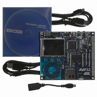
KIT DEV/EVAL FOR AVR32 AT32UC3A
Manufacturer
Atmel
Series
AVR®32r
Type
MCUr
Datasheets
1.ATAVRONE-PROBECBL.pdf
(16 pages)
2.ATEVK1104.pdf
(826 pages)
3.ATEVK1104.pdf
(90 pages)
4.ATEVK1104.pdf
(6 pages)
5.ATEVK1104.pdf
(12 pages)
Specifications of ATEVK1104
Contents
Evaluation Board, Software and Documentation
Processor To Be Evaluated
AT32UC3A3
Data Bus Width
32 bit
Interface Type
USB, SPI, USART
Silicon Manufacturer
Atmel
Core Architecture
AVR
Core Sub-architecture
AVR UC3
Silicon Core Number
AT32UC3A3256
Silicon Family Name
AVR
Kit Contents
Board CD Docs
Rohs Compliant
Yes
For Use With/related Products
AT32UC3A3
Lead Free Status / RoHS Status
Lead free / RoHS Compliant
Available stocks
Company
Part Number
Manufacturer
Quantity
Price
Company:

Part Number:
ATEVK1104
Manufacturer:
Atmel
Quantity:
135


30.7.4
Figure 30-30. Example of DMA Chained List
32058J–AVR32–04/11
USB DMA Channel X Registers
(Current Transfer Descriptor)
Next Descriptor Address
Memory Area
Data Buffer 1
Data Buffer 2
Data Buffer 3
HSB Address
USB DMA Operation
Control
Status
USB packets of any length may be transferred when required by the USB controller. These
transfers always feature sequential addressing. These two characteristics mean that in case of
high USB controller throughput, both HSB ports will benefit from “incrementing burst of unspeci-
fied length” since the average access latency of HSB slaves can then be reduced.
The DMA uses word “incrementing burst of unspecified length” of up to 256 beats for both data
transfers and channel descriptor loading. A burst may last on the HSB busses for the duration of
a whole USB packet transfer, unless otherwise broken by the HSB arbitration or the HSB 1 kbyte
boundary crossing.
Packet data HSB bursts may be locked on a DMA buffer basis for drastic overall HSB bus band-
width performance boost with paged memories. This is because these memories row (or bank)
changes, which are very clock-cycle consuming, will then likely not occur or occur once instead
of dozens of times during a single big USB packet DMA transfer in case other HSB masters
address the memory. This means up to 128 words single cycle unbroken HSB bursts for bulk
pipes/endpoints and 256 words single cycle unbroken bursts for isochronous pipes/endpoints.
This maximal burst length is then controlled by the lowest programmed USB pipe/endpoint size
(PSIZE/EPSIZE) and DMA channel byte length (CH_BYTE_LENGTH).
The USB controller average throughput may be up to nearly 1.5 Mbyte/s. Its average access
latency decreases as burst length increases due to the 0 wait-state side effect of unchanged
pipe/endpoint. Word access allows reducing the HSB bandwidth required for the USB by 4 com-
pared to native byte access. If at least 0 wait-state word burst capability is also provided by the
other DMA HSB bus slaves, each of both DMA HSB busses need less than 1.1% bandwidth
allocation for full USB bandwidth usage at 33 MHz, and less than 0.6% at 66 MHz.
Next Descriptor Address
Transfer Descriptor
HSB Address
Control
Next Descriptor Address
Transfer Descriptor
HSB Address
Control
Next Descriptor Address
Transfer Descriptor
HSB Address
Control
AT32UC3A
NULL
529
Related parts for ATEVK1104
Image
Part Number
Description
Manufacturer
Datasheet
Request
R

Part Number:
Description:
DEV KIT FOR AVR/AVR32
Manufacturer:
Atmel
Datasheet:

Part Number:
Description:
INTERVAL AND WIPE/WASH WIPER CONTROL IC WITH DELAY
Manufacturer:
ATMEL Corporation
Datasheet:
Part Number:
Description:
Low-Voltage Voice-Switched IC for Hands-Free Operation
Manufacturer:
ATMEL Corporation
Datasheet:
Part Number:
Description:
MONOLITHIC INTEGRATED FEATUREPHONE CIRCUIT
Manufacturer:
ATMEL Corporation
Datasheet:
Part Number:
Description:
AM-FM Receiver IC U4255BM-M
Manufacturer:
ATMEL Corporation
Datasheet:
Part Number:
Description:
Monolithic Integrated Feature Phone Circuit
Manufacturer:
ATMEL Corporation
Datasheet:
Part Number:
Description:
Multistandard Video-IF and Quasi Parallel Sound Processing
Manufacturer:
ATMEL Corporation
Datasheet:
Part Number:
Description:
High-performance EE PLD
Manufacturer:
ATMEL Corporation
Datasheet:
Part Number:
Description:
8-bit Flash Microcontroller
Manufacturer:
ATMEL Corporation
Datasheet:
Part Number:
Description:
2-Wire Serial EEPROM
Manufacturer:
ATMEL Corporation
Datasheet: